Control valves are critical components in industrial processes, acting as the final control element. They regulate fluid flow or pressure. Typically, they’re equipped with actuators (pneumatic, electric, or gear handwheel), positioners, handwheels, solenoid valves, limit switches, or other accessories to function effectively.
Control Valve Types.
Control valves are essential components in various industrial processes for regulating the flow, pressure, temperature, and other parameters of fluids. There are several types of control valves, each designed for specific applications and control requirements. Here are some common types of control valves:

- Globe Valve: Globe valves are versatile and widely used for control applications. They provide linear or equal percentage flow characteristics. The valve’s plug and seat design allows for fine control of flow rates. Globe valves are suitable for both throttling and on-off control.
- Ball Valve: Ball valves are known for their fast open-close action and are suitable for on-off control. They have a simple design with a ball-shaped closure element that rotates within the valve body. Ball valves provide good shutoff capabilities and are commonly used in applications where tight shut-off is essential.
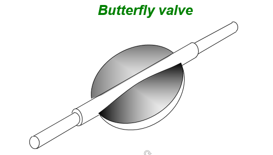
- Butterfly Valve: Butterfly valves offer a compact design and quick quarter-turn operation. They are suitable for larger pipes and applications that require high flow rates. Butterfly valves provide a cost-effective solution for both on-off and throttling control.
- Plug Valve: Plug valves have a cylindrical or tapered plug that rotates within the valve body to control the flow. They are used for on-off applications and can provide tight shut-off. Plug valves are often used in applications with slurry and abrasive fluids.
- Needle Valve: Needle valves have a long, tapered needle-like stem that allows for precise flow control. They are commonly used in applications that require fine adjustments of flow rates, such as in laboratory settings.
- Diaphragm Valve: Diaphragm valves use a flexible diaphragm to regulate flow. They are suitable for controlling corrosive or viscous fluids and are often used in pharmaceutical, food, and chemical industries.
- Control Ball Valve: Control ball valves are modified ball valves with special trims that provide better control characteristics. They are suitable for applications requiring modulating control.
- Angle Valve: Angle valves have an angled body design, allowing them to handle high-pressure drop applications. They are commonly used in steam and gas flow control.
- Three-Way Valve: Three-way valves have three ports and are used to divert or mix flow from two sources. They are commonly used in applications where flow needs to be redirected.
- Piston Valve: Piston valves use a piston-like closure element to control flow. They are suitable for applications requiring high-pressure and high-temperature control.
- Gate Valve: Control gate valves are designed for throttling and flow control. They have a special trim that provides better control characteristics compared to standard gate valves.
- Plug Valve: Similar to control gate valves, control plug valves are designed for better flow control with a specialized trim.
The choice of control valve type depends on factors such as the application, flow characteristics, pressure, temperature, control requirements, and the specific fluid being handled. Each type has its advantages and limitations, making it important to select the appropriate valve for the intended application to achieve optimal control performance.
1. Globe Type Control Valves.
In our list globe valve is first control valve types. A globe valve is a type of linear motion valve that is widely used for regulating and controlling the flow of fluids within pipelines. Its design features a disc or plug that moves perpendicularly to the flow direction to open or close the valve. The disc is connected to a stem that is controlled by a handwheel or actuator. Globe valves are known for their precise throttling capabilities and can be used for a wide range of flow control applications, making them a common choice in industries such as oil and gas, water treatment, power generation, and more.
Advantages.
- Rugged construction.
- Linear relationship between the control signal and valve stem movements.
- Wide range of trims and accessories allowing the flow characteristics to be tailored to the application.
- Anti-cavitation trim for liquid applications.
- Noise attenuation trim for gaseous applications.
- Wide range of designs for corrosive, abrasive, high temperature and high pressure applications.
- Relative small values for dead band and hysteresis.
Disadvantages.
- At larger sizes, globe valve is expensive compared with other styles.
- Relatively high mass and a lower capacity than, for example, ball of butterfly valves.
Cage Guided Globe Valve.

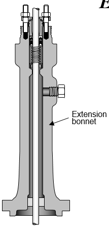
Extension bonnet.
Extended bonnet in which the stuffing box is located further away from the process medium allows the process medium temperature to be extended up to 800 °C or more.
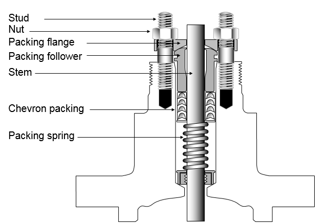
Packing box trim.
Includes various combinations of all, or part of, the following:
- Packing
- Packing nut
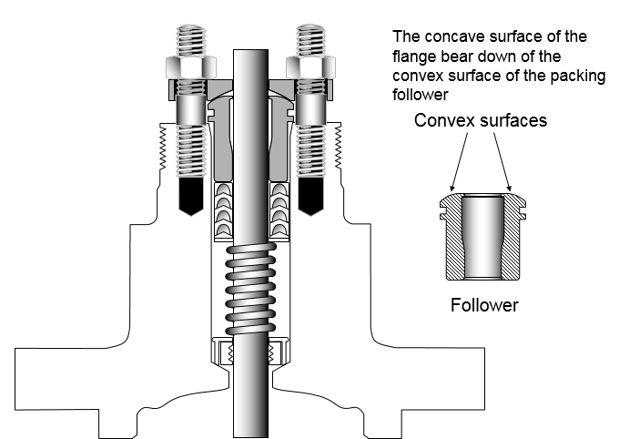
- Packing follower
- Lantern ring
- Packing spring
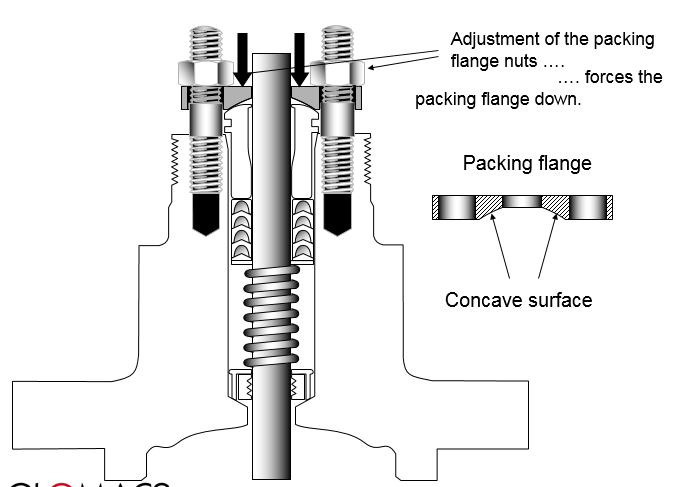
- Packing flange
- Packing flange studs or bolts
- Packing flange nuts
- Packing ring
- Packing wiper ring
- Felt wiper ring
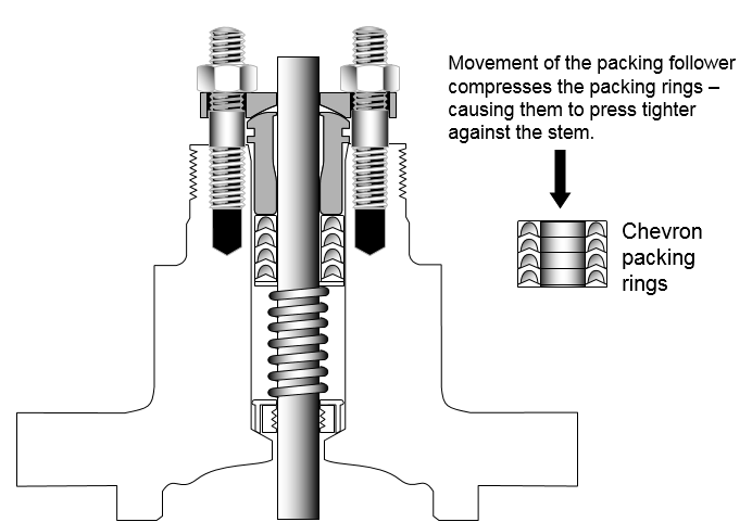
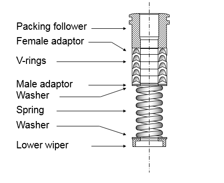
PTFE V-ring packing.
Construction
- Moulded in PTFE V or chevron rings
- Spring loaded and self adjusting
Application
- Resistant to most known chemicals
- Handles strong acids and alkali solutions
- Not suitable for molten alkali metals.
- Suitable for temperatures from –40 up to 230°C
- Requires extremely smooth stem finish to seal properly (1 μm)
- Lubrication not required
- Not suitable for nuclear service (PTFE destroyed by radiation)
Typical standard V-ring packing arrangement
Graphite filament packing.
Construction
- Light weight graphite/carbon fibres, twisted together and interlock braided.
- Contains a special lubricant to provide a bearing film and prevent wicking.
Application
- Severe service packing.
- Handles strong acids and alkali solution except fuming nitric acid, oleum and fluorine.
- Handles high temperatures (up to 650°C) and extremely high shaft speeds.
- Produces high stem friction
- Lubrication not required
Typical double graphite packing arrangement

Electrochemical series

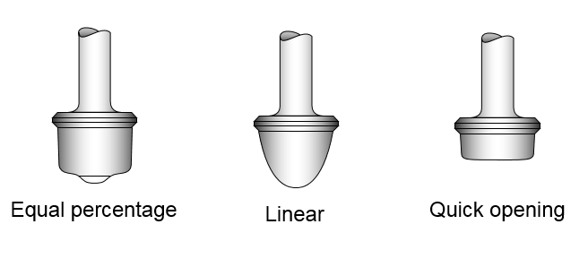
Read Also: Valve plug contours.
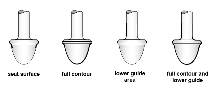
Plug hard facing variations.
Plug valve hard facing variations refer to different configurations of the sealing surfaces and guide areas on the plug valve, specifically designed to meet specific application requirements. These variations aim to address issues related to wear, corrosion, and flow control in different environments. Let’s take a closer look at these hard facing variations:
- Seat Surface Hard Facing: In this variation, only the sealing surfaces, where the plug and the valve body make contact to achieve shut-off, are subjected to hard facing. This method enhances the durability of the sealing surfaces, reducing wear and improving the valve’s ability to maintain a tight seal over multiple cycles.
- Full Contour Hard Facing: Full contour hard facing involves applying a wear-resistant material across the entire plug surface, including both the sealing surfaces and the surrounding areas. This comprehensive hard facing provides protection against wear, erosion, and corrosion not only on the sealing surfaces but also on other parts of the plug that come into contact with the flow media.
- Low Guide Area Hard Facing: In this variation, the guide area of the plug, which ensures proper alignment and smooth operation of the valve, is subjected to hard facing. This is particularly beneficial in applications where abrasive particles or corrosive fluids can cause wear and damage to the guide area. Hard facing the guide area helps maintain precise plug movement and extends the valve’s operational life.
- Full Contour and Low Guide Area Hard Facing: This approach combines both full contour hard facing and hard facing of the guide area. It provides comprehensive protection to the plug, ensuring wear resistance on both the sealing surfaces and the guide area. This variation is suitable for applications where wear, erosion, and corrosion are significant concerns.
The choice of plug valve hard facing variation depends on the specific challenges posed by the operating conditions and the characteristics of the fluid being handled. Factors such as abrasiveness, corrosiveness, temperature, pressure, and frequency of operation all play a role in determining the most suitable hard facing configuration.
Seat Retention.
Seat retention in valves refers to the ability of the valve’s seating surfaces to maintain their position and integrity under different operating conditions. It ensures that the sealing surfaces, such as the plug and the seat in a plug valve, remain securely in place and effectively prevent the flow of fluid in the closed position of the valve. Seat retention is crucial for achieving reliable shut-off and leak-tight performance in various industrial applications.
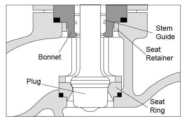
Single seat top guided control valve showing details of the plug and seat.
Balanced port

Bar Stock
Can be machined from any metallic bar stock material, or even plastic Often specified for corrosive applications. When exotic metal alloys are required, a bar stock body is normally less expensive than a body produced from a casting.

2. Gate Type Control Valves.
2nd no is gate valve of control valve types. A gate valve is a type of valve used to control the flow of fluids within a pipeline. It operates by raising or lowering a rectangular or circular gate or disc to either allow or block the flow of the fluid. Gate valves are typically operated in either fully open or fully closed positions and are not suited for throttling applications due to potential erosion and damage to the gate.
The design of a gate valve includes a gate or disc, a stationary body with ports, and a stem connected to an actuator or handwheel. When the gate is lifted, the flow is allowed, and when it’s lowered, the flow is blocked. Gate valves are commonly used in various industries, including oil and gas, water distribution, wastewater treatment, and more.
- The gate valve is an excellent valve for service that requires either full or no flow.
- When fully open, the gate valve has no flow restriction — with the flow area equal to the full cross-sectional area of the line.
- Since flow is straight through the line, pressure drop across a gate valve is only about 1/50th of that of a globe valve of comparable size.

Advantages
- can be left open or closed on a variety of water, gas and chemical duties for long periods of time with the sure knowledge of satisfactory operation when required.
Disadvantages
- close regulation of flow is not possible because throttling only occurs when the valve is in an almost shut position, where most of the flow reduction occurs.
- repeated movement of the disc near the point of closure against upstream pressure can create a drag between the seat on the downstream side and may gall or score the seat faces.
- the high-velocity flowing liquid impinging against a partially open disc or wedge produces vibration that can damage seating surfaces and score the downstream side.


3. Pinch Type Control Valves.
3rd is pinch valve of control valve types. A pinch valve is a type of valve used to control the flow of fluids through a pipe or tubing by pinching or compressing a flexible tube or sleeve. It operates on the principle of using mechanical force to constrict the flow passage, effectively stopping the flow of the fluid. Pinch valves are simple in design and offer advantages in applications where cleanliness, reliability, and ease of maintenance are crucial.


The basic components of a pinch valve include:
- Body or Housing: The main body of the valve contains the flexible tubing or sleeve that is pinched to control the flow. It typically has inlet and outlet ports to connect to the pipeline.
- Flexible Sleeve: The flexible tube or sleeve is made of a material that can be easily pinched or compressed to stop the flow of the fluid. Common materials include rubber, elastomers, and various synthetic compounds.
- Pinching Mechanism: The pinch valve has a mechanism that applies pressure to the flexible sleeve to close off the flow path. This mechanism can be manual, pneumatic, or electrically actuated, depending on the application.
- Actuator: In automated systems, an actuator is used to control the pinching mechanism. Pneumatic actuators use air pressure to pinch the sleeve, while electric actuators use motors to achieve the same effect.
Working Principle: When the pinch valve is in the open position, the flexible sleeve remains unpinched, allowing fluid to flow freely through the valve. When the valve needs to be closed, the pinching mechanism is activated, applying pressure to the sleeve and squeezing it shut. This effectively stops the flow of fluid.
Advantages.
- Simple and cost effective
- excellent resistance to abrasion – ideal for use on slurries.
- turbulence is minimal — thus also increasing the life of the valve.
- may be used very effectively as control valves in a number of applications where abrasion, sewerage, and corrosion is a factor.
Disadvantages.
- very high forces are required to operate the pinch valve and keep them closed.
- at 600 kPa a force of over 8000 kg is required to close and seal a 300 mm valve.
- restricted to low pressures (below 400 kPa) and low velocities.
4. Diaphragm Type Control Valves.
4th is diaphragm valve of control valve types. A diaphragm valve is a type of valve that uses a flexible diaphragm to control the flow of fluids. The diaphragm is a flexible membrane that is pushed against a valve seat to block the flow or pulled away to allow the flow. This type of valve is commonly used for applications where cleanliness and contamination control are crucial, as the diaphragm isolates the fluid from the valve body and stem.
Diaphragm valves are known for their ability to handle corrosive and abrasive fluids, making them suitable for a wide range of industries including pharmaceuticals, chemical processing, water treatment, and more. They are available in various materials and configurations to suit different process requirements.

- Linear flow characteristics make it well suited to throttling or modulating duties at modest differential pressures.
- Wide range of applications (175°C max. and 16 bar max.).
- All working parts are isolated from the line media.
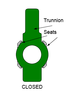
5. Ball Type Control Valves.
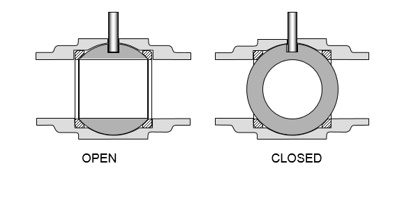
5th is ball valve of control valve types. A ball valve is a type of valve that uses a hollow, perforated, and pivoting ball to control the flow of fluids. The ball has a hole, or port, through its center that allows fluid to pass when the hole is aligned with the flow path of the valve. When the ball is rotated 90 degrees, the hole is perpendicular to the flow path and the valve is closed, stopping the flow. Ball valves are popular for their reliable sealing, easy operation, and quick on-off control.
They are commonly used in various industries and applications, including oil and gas, water distribution, industrial processes, and more. Ball valves come in different designs, such as floating ball, trunnion-mounted ball, and three-way ball valves, and they can be made from a variety of materials to handle different fluids and environments.
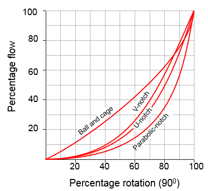
Characterised V-notch Ball Valve.
- In the characterised ball segment valve the opening between the ball and seal are modified to provide different flow characteristics.
- The V-notched ball segment produces an equal percentage flow characteristic and provides a shear-on-close action — making it suitable for slurry applications and for fluids that include fibrous and stringy material.
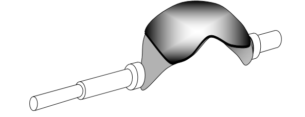
Other contours include the U-notch and parabolic-notch providing differing flow characteristics
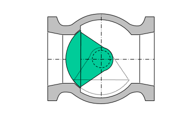
Ball Segment Valve.
- In the ball segment valve the shaft is centrally mounted to give constant contact between the segment and the seat during opening and closing.
- Suitable for both clean liquids and fibre suspensions, the seat acts like a scraper keeping the surface of the segment clean
Eccentric Shaft Segmented Ball Valve.
- In this version the shaft is located eccentrically.
- This enables the pressure between the segment and the seat to be increased by increasing the torque on the shaft.
- Typical applications are clean, hot media such as steam and gases, where it is necessary to use a stellite seat.
- Due to the eccentricity, friction between the seat and segment is avoided — resulting in increased valve life.
6. Butterfly Type Control Valves.
6th one is butterfly valve of control valve types. A butterfly valve is a type of quarter-turn valve that uses a flat, circular disc (the “butterfly”) positioned at right angles to the flow of the fluid. By rotating the disc, the valve can be opened or closed, controlling the flow of liquids, gases, or slurries.
Butterfly valves are commonly used in various industries due to their simple design, ease of operation, and versatility in regulating flow and pressure. They come in different types, including wafer, lug, and flanged, each suitable for specific applications. Following are the technical points for Butterfly valve.
- From 100 mm upwards, the ball valve tends to become bulky.
- And if manufactured of a sophisticated heat and/or corrosion resistant material can become expensive.
- This has led to the development of the butterfly valve.
- Rotation of the conventional butterfly valve is limited to about 60°.
- This is because, as the disc is rotated nearer to the fully open position the leading and trailing edges of the disc are shadowed by the shaft.
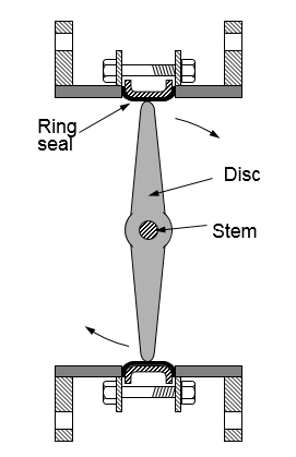
- The body of the valve is lined with an elastomeric material that is held in position in the body by either bonding or mechanical means.
- As the disc moves into the closed position, the material of the liner is an interference fit with the disc edge.
- This determines the pressure sealing capability and the torque required to close and open the valve into or from the full closed position.
Eccentric Disk Butterfly Valve.
- In the offset disc, or high performance butterfly valve, the disc is offset in two planes, resulting in an eccentric rotating or camming action.
- This results in the disc moving away from the seat after approximately I0° of rotation, and equal loading of the seat whenever the valve is closed.

- Seat designs vary from pressure energised reinforced PTFE, to the solid filled PTFE.
- Advantages include:
- better seal performance,
- lower dynamic torque
- higher allowable pressure drops.
- The improvement in seal performance is because the disc cams in and out of the seat and thus contact is made only at closure.
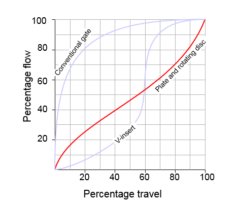
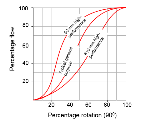
Butterfly Valve Characteristics.

If you wanna read more information about Butterfly valve and its types with details.
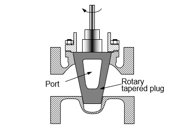
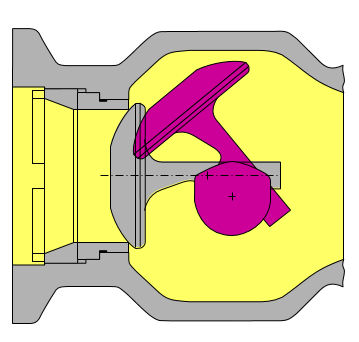
7. Plug Type Control Valves.
7th is plug valve of control valve types. A plug valve is a type of quarter-turn rotary valve that uses a cylindrical or tapered plug to control the flow of fluids through a pipeline. The plug, which is often shaped like a cylinder, can be rotated within the valve body to either allow or block the passage of the fluid. This rotational movement enables quick and efficient on-off control of the flow.
- One of the oldest valves in use
- When the plug is rotated it permits flow through the port of the plug — whilst a 90° turn in either direction completely blocks the flow path.
Eccentric plug valve – 1
- The centre of the spherical seating surface is offset from the shaft axis.
- The one piece shaft, which is connected to an actuating arm linked to the actuator piston rod, rotates the plug face in an eccentric, cam-like motion, down and forward into the seat.
- As the plug rotates into its seated position, it makes no contact with the seat until the actual moment of seating.
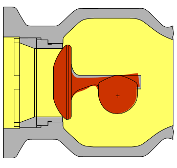
Eccentric plug valve – 2
- Once seating occurs, a positive seal between plug and seat is achieved by the elastic deformation of the plug arms
- When the plug seats, the arms ‘flex’ such that additional actuator thrust forces the plug deeper and into tighter contact with the seat.
- The shaft connection allows the plug to center itself along the shaft axis.
The angle of contact between the plug and seat lets the plug wipe larger particles off the seating surfaces yet permits no rubbing, once contact is established
Eccentric plug valve – 3
- Standard leakage classifications of metal to metal seating surfaces conform to ANSI B16.104 Class IV.
- For ANSI B16.104 Class VI (bubble tight) use is made of PTFE ` soft seat construction.
- Another feature of the Camflex valve is that only one-third the amount of force required to stroke a conventional single-seated globe valve is required of the Camflex actuator to stroke against a given pressure drop.
- The spherically shaped, eccentric rotating plug provides an inherent flow characteristic that is essentially linear.
- As the plug approaches the seat, the characteristic curve is modified as the rate of change in flow is reduced smoothly until the plug actually contacts the seat.
Eccentric plug valve – 4
- Integral extension bonnets make this valve acceptable on cryogenic fluids and temperatures to 400°C.
- It also eliminates a gasket joint at the body to bonnet interface and associated potential for leakage.
- Although not specifically designed for it, this design has proven successful on hard-to-handle moderate slurry service, ranging from alumna oxide to low-pressure oil and catalyst.
To read more types of Plug Valves.
8. Angle Type Control Valves.
An angle valve is a type of industrial valve that is designed with an inlet and outlet at a 90-degree angle to each other. This valve configuration allows for fluid flow to change direction, making it useful in applications where space constraints or piping layouts require a change in flow direction. Angle valves are commonly used in various industries to control the flow of liquids, gases, or steam.

write fantastic
Really a great article I ever happened to read. Not only this article, but so many of your bogs are very very informative. I amazed to see a few.