This article is about basic control valve complete technical guide and focusing to the engineers, technicians and supervisors. You will find lot of documents related to this article. Just navigate our website www.paktechpoint.com and find more articles. Checkout following table of contents we discussed all technical aspects of control valve.
Table of Contents
Control Valve Introduction:
Control valves play a crucial role in various industries by regulating the flow of fluids to maintain desired process conditions. They are essential components in processes where precise control over parameters like flow rate, pressure, temperature, and level is required. This article delves into the functioning, types, components, and applications of control valves.

Function of Control Valves:
Control valves are devices that modulate the flow of fluid through a system, allowing operators to control process variables. They work by adjusting the valve’s opening to regulate the flow rate and maintain the desired setpoint. This is achieved by varying the position of the valve’s internal components, such as a plug, disc, or ball, in response to signals from the control system.
Types of Control Valves:
- Globe Valves: These are common linear-motion valves that provide precise control over flow rates. They have a globe-shaped body with a movable plug or disc that regulates the flow by moving up and down.
- Butterfly Valves: These valves use a rotating disc (butterfly) to control the flow. They are known for quick operation and are suitable for large flow applications.
- Ball Valves: Ball valves use a spherical ball with a hole to control the flow. They provide tight shut-off and are commonly used for on-off control.
- Diaphragm Valves: Diaphragm valves use a flexible diaphragm to regulate flow. They are suitable for handling corrosive or abrasive fluids.
- Pinch Valves: Pinch valves use a flexible sleeve to control flow by pinching or releasing it. They are often used for slurries or fluids containing solids.
- Gate Valves: Gate valves are a type of linear motion valve used for controlling the flow of fluids in a pipeline. They operate by raising or lowering a gate-like disc (also known as a wedge) to either block or allow the flow of fluid through the valve. This simple yet effective mechanism makes gate valves well-suited for both on-off and throttling applications in various industries, including oil and gas, water treatment, chemical, and more.
- Plug valves are essential components in fluid handling systems, providing efficient on-off and flow control capabilities. These valves utilize a cylindrical or tapered plug with a passage through it, which can be rotated to either allow or obstruct the flow of fluid. This rotational movement makes plug valves versatile for a range of applications, including industries such as oil and gas, water treatment, chemical processing, and more.
- Plug valves are essential components in fluid handling systems, providing efficient on-off and flow control capabilities. These valves utilize a cylindrical or tapered plug with a passage through it, which can be rotated to either allow or obstruct the flow of fluid. This rotational movement makes plug valves versatile for a range of applications, including industries such as oil and gas, water treatment, chemical processing, and more.
Read more details one by one all types of control valves.
Components of Control Valves:
Following are the list of control valve components or parts.
- Actuator: The actuator is responsible for moving the valve’s internal components. It can be pneumatic, hydraulic, or electric, depending on the application.
- Valve Body: The valve body provides the passage for fluid flow. It houses the internal components and determines the valve’s type (globe, butterfly, etc.).
- Valve Trim: The trim consists of the plug, disc, or ball that controls the flow. It interacts with the valve seat to regulate flow rates.
- Positioner: In modern control systems, a positioner ensures that the valve’s position matches the control signal, enhancing accuracy and responsiveness.

Control Valve Pressure Drop Calculation
The basic purpose of a control valve is to control the flow of a medium in a pipe —
- turning it on or off, or
- varying it continuously.
However, a control valve designed primarily to throttle energy is not necessarily designed for shut-off purposes. These two requirements often have to be balanced or realised in separate systems.
Research studies indicate that the final control element is responsible for 60 to 70% of poor-functioning control systems. The problems lie not just with the valve itself but also with:
- the valve actuators,
- I/P converters and
- positioners.
However, probably the majority of problems can be attributed to oversized valves and undersized actuators.
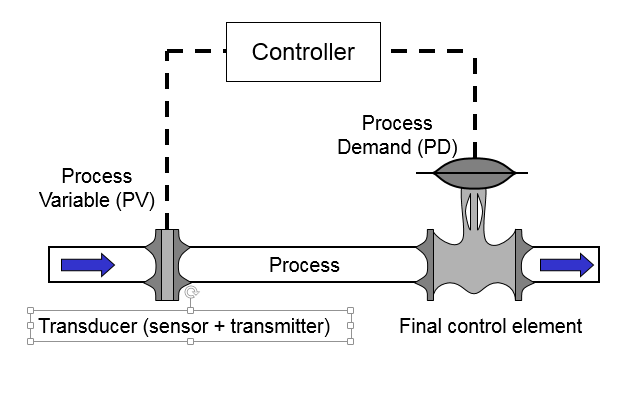
If the PD is subject to a step change, by how much will the PV change?
This is determined by what is called the Process Gain (Kp) and is given by:

Thus, for example, if we make a step change of 30% to the PD and the PV also changes by 30% then:
Process Gain (KP) = 1.
However, if the PV only changes by 15% then:
Process Gain (KP) = 0.5.
Alternatively, if the PV changes by 60% then:
Process Gain (KP) = 2.
Generally, the process gain should lie between the 0.5 and 2.0. If it is less than 0.5 then, typically, the transmitter span is too wide for good control. If the process gain is greater that 2.0, this is usually an indication that the control valve is oversized.
Bernoulli’s equation.

where:
Q = flow rate;
k = constant;
Cd = discharge coefficient;
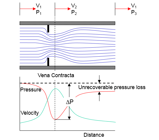
ΔP = differential pressure (P1 – P2); and
ρ = density of fluid.

where:
Q = flow rate;
Cv = valve flow coefficient;
ΔP = differential pressure (P1 – P2); and
SG = specific gravity of fluid (water at 60°F =1.0).
Valve Flow Coefficient of Control Valve
In the realm of fluid dynamics and process control, the term “CV value” refers to the Flow Coefficient of a control valve. This numerical value is a crucial parameter used to quantify the flow capacity of a valve under specific conditions. The CV value is a pivotal factor in selecting the appropriate control valve for a given application, ensuring optimal performance and efficiency.
The valve flow coefficient, Cv, is an index used to measure the capacity of a control valve.
Cv is determined experimentally, using water as the test fluid, for each style and size of valve with the valve either fully open or at a given valve opening — usually stated as a percentage of maximum travel.
Numerically, Cv is defined as:
- the number of US gallons per minute
- of water at 60°F
- which will pass through a given flow restriction
- with a pressure drop of 1 psi across the valve
CV values

Flow Coefficient (CV) Definition:
The Flow Coefficient, often denoted as CV, is a dimensionless number that represents the flow rate of a fluid through a valve in relation to the pressure drop across the valve. It quantifies the flow capacity of a valve by establishing a standardized measure for comparison across different valve sizes and types.
Mathematically, the CV value is calculated using the following equation:
The correct formula for calculating the Flow Coefficient (Cv) for a control valve is given by:
Cv = Q √ (SQ/P)
Where:
- Cv is the Flow Coefficient
- Q is the flow rate of the fluid (expressed in gallons per minute, liters per minute, etc.)
- SQ is the specific gravity of the fluid
- ΔP is the pressure drop across the valve (expressed in pounds per square inch, bar, etc.)
Interpreting the CV Value:
A higher CV value indicates a larger flow capacity of the valve, implying that the valve can handle a greater volume of fluid for a given pressure drop. Conversely, a lower CV value suggests a smaller flow capacity.
Importance in Valve Selection:
The CV value is a fundamental parameter in the process of selecting an appropriate control valve for a specific application. Here’s how it works:
- Flow Requirements: By knowing the required flow rate and the allowable pressure drop, engineers can calculate the desired CV value for the valve.
- Valve Sizing: Manufacturers provide CV values for their valve products, allowing engineers to match the required CV value with the available options. The selected valve should have a CV value that meets or slightly exceeds the calculated value.
- Efficiency: A valve with the right CV value ensures that the fluid flow is regulated efficiently, preventing excessive pressure drops or insufficient flow rates.
- Performance Prediction: The CV value aids in predicting the performance of a control valve within a system. It helps engineers anticipate how the valve will behave under specific operating conditions.
- Accurate Control: A well-matched control valve, with a CV value tailored to the application, enables precise control over flow rates, pressure, and other process parameters.
Application Variability:
It’s important to note that the CV value is not a fixed constant for a valve. It can vary depending on factors such as valve type, size, design, and the fluid being controlled. Additionally, control valves may have inherent flow characteristics (linear, equal percentage, etc.) that influence their performance.
The Flow Coefficient (CV value) is a critical metric used to determine the flow capacity of a control valve. By considering the desired flow rate and pressure drop, engineers can select a control valve with an appropriate CV value to ensure accurate and efficient fluid regulation in various industrial processes.
Why Choked Flow is necessary for Engineers?
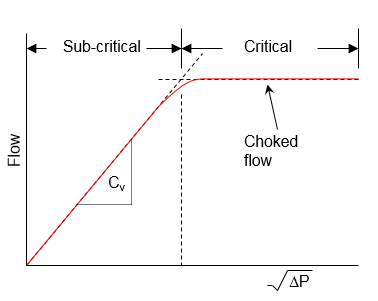
Choked flow, also known as critical flow, in a control valve occurs when the flow rate of a fluid through the valve reaches a point where the velocity of the fluid approaches the speed of sound. In this condition, further reduction in downstream pressure does not result in an increase in flow rate. Choked flow is a phenomenon that happens when the fluid velocity reaches the local sonic velocity, and no further acceleration of the fluid is possible due to the limitations of the speed of sound.
In practical terms, when a fluid passes through a control valve and the pressure drop across the valve becomes significant, the fluid velocity can increase to the point where it reaches sonic velocity. At this point, even if the downstream pressure continues to decrease, the flow rate remains constant or even decreases due to the restriction caused by the sonic velocity limit.
Choked flow has implications for control valve sizing and performance. When designing control systems, engineers need to ensure that the valve is not operating in a choked flow condition if precise control of flow rate is required. Additionally, choked flow can lead to noise, vibration, and erosion within the valve and downstream piping.
Engineers and operators must consider choked flow conditions when selecting and sizing control valves to ensure that the valve operates within its intended range and provides accurate control of the fluid flow while avoiding the limitations associated with choked flow.
- Flow is only proportional to √ΔP within the sub-critical flow region.
- If the differential pressure is further increased, a point is reached where no further flow increase occurs —despite increasing the differential pressure.
- Called ‘choked flow’ (critical flow) and is the maximum flow rate possible through that valve.
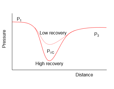
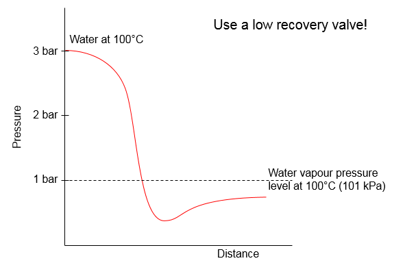
High vs. Low Recovery Valves
- A streamlined valve will dissipate less energy through the restriction and will have more energy downstream for recovery to a higher pressure.
- In a less streamlined valve larger amounts of energy are dissipated through the restriction and less energy will be available downstream for recovery to a higher pressure.
- Streamlined valves produce relatively higher velocities through their restriction than do less streamlined, restrictive valves.
- Velocity, being inversely proportional to pressure, suggests lower pressure at the vena contracta with high recovery streamlined valves .
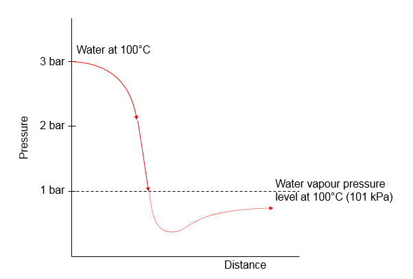
Flashing in Control Valve
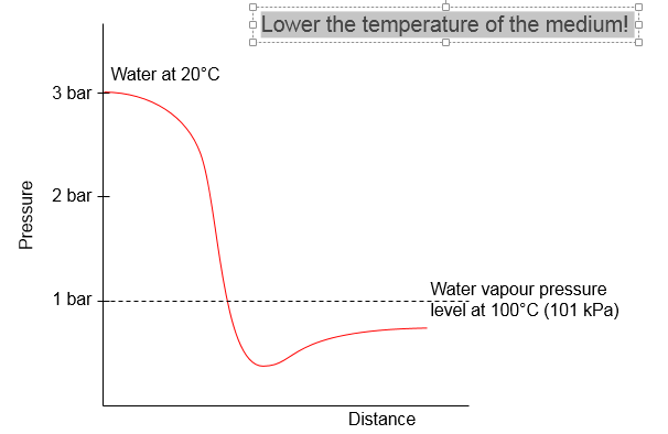
Flashing in a control valve refers to the phenomenon where a liquid undergoes a rapid phase change from a liquid to a vapor due to a sudden drop in pressure. This typically occurs when a high-pressure liquid flows through a control valve and experiences a significant pressure reduction as it moves to a lower-pressure region. The sudden pressure drop causes the liquid to vaporize and form vapor bubbles within the fluid stream.
Flashing is a dynamic process that can lead to several undesirable effects:
- Noise and Vibration: The rapid formation and collapse of vapor bubbles can create noise and vibration within the control valve and downstream piping, which can be problematic for the overall system.
- Cavitation: Flashing can lead to cavitation, a destructive phenomenon where the vapor bubbles collapse with high intensity, causing micro-explosions. Cavitation can damage the valve internals and other components, leading to reduced valve performance and increased maintenance.
- Erosion: The collapse of vapor bubbles during cavitation can cause erosion and pitting on the valve surfaces and downstream piping, leading to material degradation over time.
- Reduced Accuracy: Flashing can disrupt the expected flow characteristics of the control valve, affecting its ability to accurately regulate flow rates and process conditions.
Flashing Problem Solution:
To eliminate the effects of flashing, engineers and operators may employ various strategies:
- Pressure Recovery: Reducing the pressure drop across the valve can help minimize the occurrence of flashing. This can be achieved by using multiple stages of pressure reduction or employing a throttling control strategy.
- Anti-Flash Geometry: Some control valve designs incorporate anti-flash geometry in the valve trim to reduce the likelihood of flashing by controlling the pressure drop across the valve.
- Flow Control Strategy: Employing control strategies that minimize sudden pressure drops, such as gradual opening and closing of the valve, can help prevent flashing.
- Material Selection: Using materials that are resistant to erosion and cavitation damage can help mitigate the negative effects of flashing.
- Flow Modeling: Sophisticated computational fluid dynamics (CFD) simulations can help predict and analyze the occurrence of flashing, allowing engineers to optimize valve design and operation.
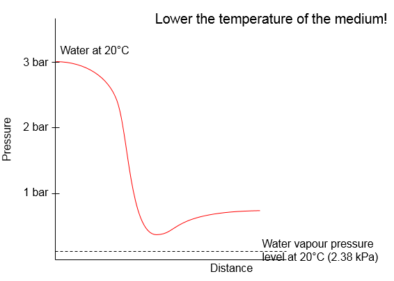
Or Lower the temperature of the medium!
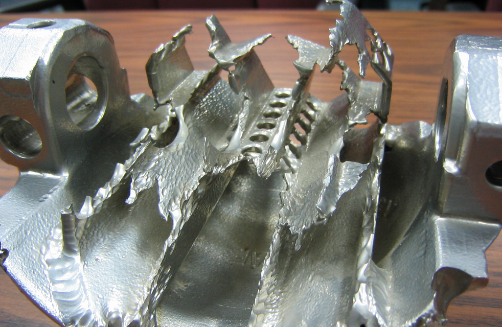
Even worse…
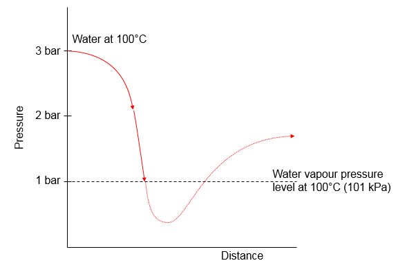
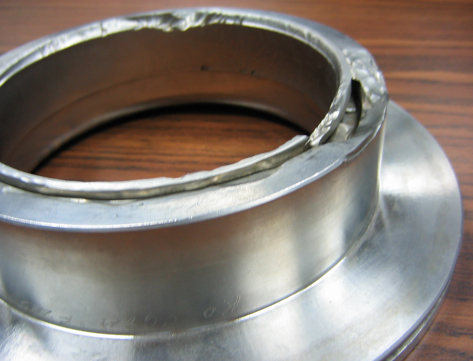
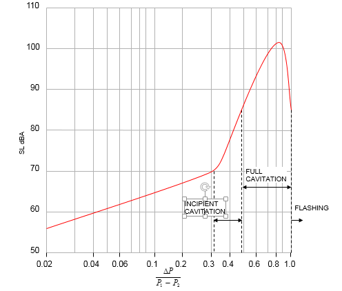
Cavitation in Valve
This two-stage phenomenon, vapour bubble formation and their subsequent collapse, is known as cavitation. If the bubbles collapse on or near solid surfaces, material is chipped away. The amount of damage in a short period of time can be extensive and eventually prevents the control valve from performing its intended function.

Cavitation in a valve is a phenomenon that occurs when the pressure of a fluid drops to the point where it vaporizes and forms small vapor bubbles or cavities. These bubbles then collapse when they move to a region of higher pressure, creating shockwaves and intense forces that can lead to damage and erosion of the valve and its components.
Cavitation typically occurs in control valves and other fluid-handling equipment when the fluid’s velocity increases and its pressure decreases, often due to changes in flow rate or direction. As the fluid passes through the valve and its pressure drops below the vapor pressure, some of the liquid turns into vapor, forming cavities. When these vapor bubbles move to a higher-pressure region, they collapse violently, creating shockwaves that can generate high-frequency noise, vibration, and erosion.
Effects of Cavitation in Valves:
- Noise and Vibration: Cavitation can create loud noise and vibration, which not only affect the surrounding environment but can also lead to discomfort for workers and damage to nearby equipment.
- Erosion: The implosion of vapor bubbles generates intense localized forces that can cause erosion on the valve’s internal components, including the valve trim and seat.
- Reduced Performance: As cavitation progresses, it can lead to pitting and erosion of the valve’s surfaces, altering its shape and reducing its performance and efficiency.
- Increased Maintenance and Downtime: The damage caused by cavitation necessitates frequent maintenance and repair of valves, leading to increased downtime and operational costs.
- Degraded Control: Cavitation can disrupt the valve’s control performance by causing unpredictable changes in flow rates and pressure drops, making it challenging to maintain stable and accurate control.
Preventing Cavitation:
- Valve Sizing: Properly sizing the valve based on the application’s flow conditions and characteristics can help avoid excessive pressure drops and velocities that lead to cavitation.
- Trims and Anti-Cavitation Solutions: Engineers can use specialized valve trims, such as anti-cavitation or pressure-reducing trims, that gradually reduce pressure and minimize the formation of vapor bubbles.
- Pressure Management: Installing pressure-reducing valves or pressure regulators upstream of the control valve can help maintain a more balanced pressure across the valve, reducing the likelihood of cavitation.
- Fluid Properties: Understanding the fluid’s characteristics, including its vapor pressure and temperature, is crucial in determining the potential for cavitation.
- Valve Design: Modern valve designs may incorporate features that help minimize cavitation, such as streamlined flow paths and specialized trim designs.
By addressing cavitation issues through proper valve selection, sizing, and design, engineers can ensure the reliable and efficient operation of control valves while minimizing the negative effects of cavitation.
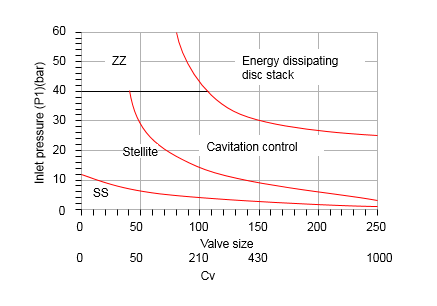
Trim Selection in Control Valve
Trim selection in valve design refers to the process of choosing the appropriate internal components of a valve that come into contact with the flowing fluid. The trim components, such as the valve disc, seat, and other elements, directly influence the valve’s performance, control characteristics, and ability to handle specific types of fluids and conditions. Trim selection is a critical aspect of valve design to ensure optimal functionality and efficiency.
Key Factors in Trim Selection:
- Fluid Properties: The characteristics of the fluid being handled, such as its type, temperature, pressure, viscosity, corrosiveness, and erosiveness, play a crucial role in determining the suitable trim materials. Fluid properties influence the choice of materials that can withstand the fluid’s effects without degradation or damage.
- Flow Control Requirements: The desired flow characteristics, such as linear, equal percentage, or quick opening, influence the design of the valve trim. Different trims are designed to provide specific control behaviors based on the application’s requirements.
- Cavitation and Erosion Resistance: If the fluid has the potential for cavitation or contains abrasive particles, the trim must be selected to resist cavitation erosion and maintain long-term reliability.
- Pressure Drop: Different trim designs can impact the pressure drop across the valve. The chosen trim should minimize pressure loss while ensuring accurate control.
- Material Compatibility: The compatibility of trim materials with the fluid ensures that there is no chemical reaction, corrosion, or contamination that could compromise the fluid’s quality.
- Temperature Range: High or low-temperature applications require trim materials that can withstand the temperature extremes without deformation or loss of performance.
- Size and Type of Valve: The trim selection may vary based on the valve size and type, such as globe, gate, butterfly, or ball valves.
- Regulatory and Industry Standards: The valve trim must adhere to industry standards and regulations governing the specific application or industry.
Types of Valve Trims:
- Standard Trim: Suitable for general applications with moderate conditions, standard trim provides basic functionality and control.
- Low Noise Trim: Designed to minimize noise generated during fluid flow, low noise trims are essential for applications where noise reduction is critical.
- Anti-Cavitation Trim: Specifically designed to mitigate cavitation effects, this trim reduces the risk of damage and erosion caused by cavitation.
- Erosion-Resistant Trim: Ideal for handling abrasive fluids, erosion-resistant trim materials withstand the erosive effects of particles in the fluid.
- High-Temperature Trim: Engineered to withstand high temperatures without deterioration, this trim is used in applications involving extreme heat.
- Cryogenic Trim: Designed to operate in cryogenic conditions, this trim remains effective and reliable at very low temperatures.
Trim selection involves a balance between the specific application requirements, valve design, and material compatibility. Engineers must carefully consider these factors to ensure that the chosen trim optimizes valve performance, enhances control accuracy, and prolongs the valve’s operational life.
Noise in Valve
Noise in valves is a phenomenon characterized by the generation of unwanted sound during the operation of a valve. This sound can range from minor vibrations and humming to loud and disruptive noise levels. Valve noise can be caused by various factors related to fluid flow, pressure differentials, and the valve’s internal components. It is essential to understand the sources of valve noise and implement measures to minimize or eliminate it, as excessive noise can affect equipment performance, worker safety, and overall process efficiency.
Key Sources of Valve Noise:
- Cavitation: When the pressure of a fluid drops below its vapor pressure, bubbles form and collapse as the fluid flows through the valve. The collapsing bubbles generate shockwaves that result in noise. Anti-cavitation measures, such as selecting the appropriate valve trim and maintaining sufficient pressure, can reduce this noise source.
- Aeration: The presence of air or gas in the fluid can cause turbulence and vibration, leading to noise. Proper degassing and venting of the fluid before it enters the valve can help reduce aeration-related noise.
- Flow Turbulence: Rapid changes in fluid velocity, especially at high flow rates, can cause turbulence and eddies in the fluid, resulting in noise. Proper valve sizing and design can minimize turbulent flow and subsequent noise.
- Pressure Drops: Rapid changes in pressure across the valve can lead to turbulence, which generates noise. Pressure reduction devices, such as orifices, can be installed upstream of the valve to minimize pressure drops.
- Valve Type and Design: Different valve types have varying noise characteristics. Globe valves and control valves tend to produce more noise due to their design and the redirection of flow. Proper valve selection based on the application’s noise requirements can help mitigate this issue.
- Valve Actuation: The method of valve actuation, such as electric, pneumatic, or hydraulic, can influence noise levels. Some actuation methods, like rapid opening or closing, can induce noise. Implementing gradual valve movements and using damping techniques can help reduce actuation-related noise.
- Material and Coatings: The materials used in the valve construction can affect noise levels. In some cases, materials with high friction can cause vibrations and noise. Applying suitable coatings or selecting low-friction materials can help minimize noise.
- Valve Position: The position of the valve (open, closed, or partially open) can impact noise levels. Positioners and controllers can help maintain a steady valve position, minimizing noise generated by valve movement.
Methods to Reduce Valve Noise:
- Valve Selection: Choosing the appropriate valve type, design, and size based on noise requirements can significantly reduce noise generation.
- Anti-Cavitation Trim: For valves prone to cavitation, using anti-cavitation trims can minimize noise by preventing the formation of vapor bubbles.
- Flow Straighteners: Installing flow straighteners or diffusers upstream of the valve can help reduce turbulence and subsequent noise.
- Noise Absorbing Materials: Applying noise-absorbing materials, such as coatings or liners, to the valve’s interior surfaces can help dampen noise.
- Sound Insulation: Encasing the valve and its associated piping in sound-absorbing enclosures can prevent noise propagation to the surrounding environment.
- Controlled Actuation: Implementing controlled and gradual valve actuation can prevent rapid pressure changes and turbulence-induced noise.
- Valve Maintenance: Regular maintenance and inspection of valves can help identify and address issues that contribute to noise generation.
Managing valve noise is crucial to ensuring a safe and comfortable working environment, preventing equipment damage, and maintaining process efficiency. By identifying the sources of noise and employing appropriate mitigation strategies, engineers and operators can effectively reduce or eliminate valve-related noise issues.
Applications of Control Valves:
Control valves are used in a wide range of industries and applications, including:
- Oil and Gas: For regulating flow, pressure, and level in pipelines and processing units.
- Chemical Processing: To control the mixing, blending, and transfer of chemicals.
- Water Treatment: In municipal water supply systems and wastewater treatment plants.
- Power Generation: In steam, gas, and nuclear power plants for controlling steam flow and temperature.
- Food and Beverage: For managing the flow of ingredients, additives, and cleaning solutions.
- Pharmaceuticals: To regulate the flow of liquids and gases in drug manufacturing processes.
Control valves are integral to industrial processes that require precise control over fluid parameters. With various types, components, and applications, these valves contribute to efficient and safe operations across multiple industries. Their ability to maintain desired process conditions makes them indispensable tools for achieving optimal process performance and product quality.