Guys for each rotating machinery vibration plays vital role for that to maintain the machinery and prior notification to avoid from damage. Vibraiton Rod Drop Measurement is the case where we measure displacment position of piston. Here we disucss in brief.
First defining Rod Drop
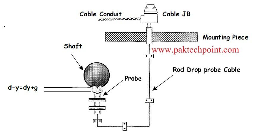
Rod drop probe is simply the vibration probe. It used in Positive displacement compressors or piston cylinder type compressors for measuring the position of the rod OR Calculate the wear (dp) on the rider ring as shown in figure .
How Vibraiton Rod Drop is Measured
The cylinder assembly data table specifies the maximum value of rod lowering dX due to the maximum wear dP on the rider ring. This value has been calculated taking into account of
Shows Piston Cylinder Assembly with Rod Drop Probe
How Rod Drop is Measured

- Thickness of new rider ring
- Depth of rider ring groove on piston
- The minimum projection of rider ring
- Geometry ofpiston rod and cross head assem
- Thus, dx = dP x (L – L1) / L
With the piston rod positioned at the lower dead center, the sensor will be placed at a distance,
dX=dx+g
Where g is the clearance which in condition of maximum wear will prevent direct contact between rod and sensor. In figure 9 the sensor mounting is shown.
System is calibrated to display O mm on the monitor when the distance between sensor and rod is dX. During normal operation the reading on monitor will give the distance in mm by which the rod has lowered. The alarm limit is set 1 mm and danger limit is set 1.5 mm (if rod is lowered by this value then the compressor will be stopped).
Please see also: BASIC CONCEPT OF VIBRATION SYSTEM
To calculation wear on piston rider ring by the value on monitor, use formula,
dp = (Reading on monitor)x (L- Ll) / L
Where in our case,
(L- Ll) / L = 0.66 for 3rd stage (L- Ll) / L = 0.68 for 4th stage
Advantages of Rod Drop Monitor
- It provides early warning of excessive rider band wear thus damage due to piston and cylinder direct contact can be prevented.
- It accurately determines rider ring wear thus utilizing maximum life of rider ring.
- It increases on-line operation and minimizes maintenance expenditure.
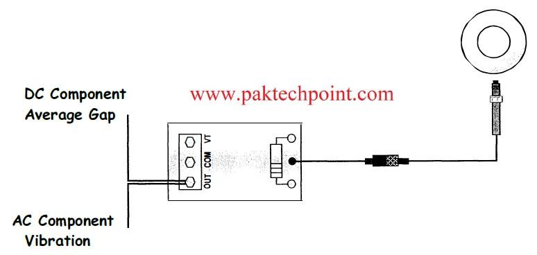
Measurement of Position and Vibration By proximity Transducer
If there is no vibration then the output of system is a de voltage that represents the distance of the shaft from transducer. When the shaft starts vibrating, it does so around that original position. That vibration adds an AC component to the signal on top of the original DC component. A proximity transducer system used for any application will always output a DC component that represents position, and an AC components vibration as shown in figure.
Frequency Response of Rod drop
Advantages and Tradeoff of ROD DROP
Advantages;
- It can measure vibration and position of shaft. (Response from Oto 10 KHz)
- It measures direct shaft motion without contact.
- It can provide speed and Keyphasor reference signal.
- It has long term reliability.
- It can provide slow roll infonnation.
- Its calibration check is simple.
Trade-off
- It is sensitive to material properties and surface conditions.
- Its internal installation may require planning e.g. drilling through the case.
- High frequency vibration usually results in low displacement level.
Please check also: Characteristic-check-of-proximity-transducer-probe
TARGET (GEAR) VARIABLE CONVERSIONS;
f = (RPMxPPR)/60 = (SS xPPR)/(π*D)
f = (UPMxPPU)/60 = UPHxPPU/3600
SS = (RPM xπxD)/60 = ( f x π xD)/PPR
RPM= (60 xf)/PPR = (60 xSS)/ (π*D)
D = PPR+2/DP =(SS*PPR)/F*π
DP = PPR+2/D = 25.4/M
M = 25.4/DP = 25.4 *DP /(PPR+2)
PPR = (D*DP)-2
f = Frequency in Hz or cycle per second (cps)
UPH = Unit measure per hour
PPU = Pulses per Unit measure
DP = Diametral pitch= No. of teeth in 1 inch pitch diameter
M = Metric module = NPitch diameter in mm7 No. of gear teeth
π = 3.14