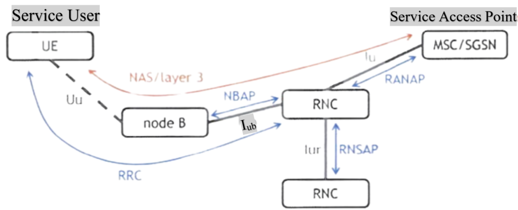
Picture below shows 3G Signalling & air interfaces.

In a UMTS network, different types of signaling are used to communicate between network elements and users. The figure shows these interfaces and their signaling types.
Service Related Signaling (Red): This type of signaling is exchanged between the user equipment (UE) and the network access points, such as the MSC (Mobile Switching Center) or the SGSN (Serving GPRS Support Node). It is also known as Layer 3 messages or NAS (Non-Access Stratum) messages. This signaling is crucial for setting up and releasing services, like making and ending voice calls. Understanding service-related signaling is essential for analyzing both mobile-originating and mobile-terminating voice calls.
Application Protocols (Blue): These protocols enable communication between different network elements. They include the RRC (Radio Resource Control) application protocol, which manages the connections between the UE and the network. The blue signaling represents the application protocols that facilitate the interactions within the network infrastructure.
In this article, the primary focus will be on the signaling captured on the air interface. Specifically, on the Uu interface, both service-related signaling (NAS/Layer 3) and the RRC application protocol can be captured during drive testing. This detailed study helps in understanding how mobile-originating and mobile-terminating calls are managed and how different parts of the network communicate effectively.
UMTS Application Protocols.
- Allow communication (signalling: control plane) between different network elements.
- Technology specific (e.g. UMTS)
- UMTS application protocols:
- RRC (Radio Resource Control)
- Runs over lu and lub interface, between UE and RNC.
- NBAP (Node B Application Part)
- Used on lub interface between node B and RNC.
- RANAP (Radio Access Network Application Part)
- Used on lucs/lups interface between RNC and MSC/SGSN.
- RNSAP (Radio Network Subsystem Application Part)
- Used on lur interface between different RNCS.
- RRC (Radio Resource Control)
Remark: only RRC application protocol will be studied in detail. Can be captured on air interface during drive testing.
The application protocols in a UMTS network belong to the control plane and facilitate signaling between different network elements. These protocols are specific to UMTS, and there are four main types: RRC, NBAP, RANAP, and RNSAP.
RRC (Radio Resource Control): This protocol operates between the user equipment (UE) and the Radio Network Controller (RNC) over both the Iu and Uu interfaces. It is the only application protocol that can be captured on the air interface during drive testing. In this article, the focus will be on the RRC protocol.
NBAP (Node B Application Part): This protocol runs over the Iub interface between Node B (base station) and the RNC. It is used for tasks such as configuring the radio link on the Node B side. For example, when setting up a radio link between the UE and Node B, NBAP configures the Node B end, while RRC configures the UE end.
RANAP (Radio Access Network Application Part): This protocol operates on the Iu interface towards the MSC (Mobile Switching Center) or SGSN (Serving GPRS Support Node). One of its key roles is managing the RAB (Radio Access Bearer) configuration procedure.
RNSAP (Radio Network Subsystem Application Part): This protocol runs between different RNCs on the Iur interface. It facilitates communication and coordination between RNCs within the network.
While the RRC protocol is covered in detail in this training, the other three protocols—NBAP, RANAP, and RNSAP—are not explored as extensively. These protocols are essential for various configuration and control tasks within the UMTS network, ensuring efficient communication and resource management between network elements.
Service Related Signalling.
- Used for service setup and release.
- Between service user (UE) and service access point (MSC/SGSN).
- Service specific, but not technology specific.
- UMTS service related signalling is different for voice call and PS data session.
- 2G and 3G service related signalling can be the same for the same service type (e.g. voice call).
Service-related signaling, also known as Layer 3 messages or NAS (Non-Access Stratum) messages, is crucial for setting up and releasing services in a UMTS network. This signaling occurs between the user equipment (UE) and the network access points, such as the MSC (Mobile Switching Center) or SGSN (Serving GPRS Support Node).
NAS/Layer 3 signaling is specific to the type of service being used, like voice calls or packet-switched (PS) services, but it is not tied to a particular technology. For instance, different NAS messages are used for different services, but the same NAS messages can be used across different technologies. This means NAS messages for a PS service can be used in both GPRS and UMTS networks, and NAS messages for voice calls can be used in both GSM and UMTS networks.
This type of signaling can be captured on the air interface during drive testing, providing valuable insights into how services are managed and how the network communicates with the user equipment.
UMTS Control Plane.
- Only one RRC Connection in connected mode, no RRC Connection in idle mode.
- RRC Connection consists of typically four signalling Radio Bearers (SRB).
- SRB1, SRB2, SRB3 and SRB4.
- Used for transport of RRC application protocol and NAS/layer 3 messages.
- RRC Connection consists of typically four signalling Radio Bearers (SRB).
- Up to two lu signalling connections in connected mode (to MSC and/or SGSN), none in idle mode.

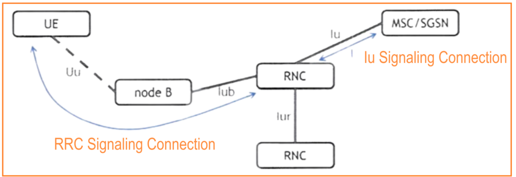
The figure above provides more details on how the UMTS control plane operates.
RRC Connection: The RRC (Radio Resource Control) connection is used to transport signaling between the user equipment (UE) and the Radio Network Controller (RNC), specifically the serving RNC. In idle mode, there is no RRC connection. However, in connected mode, there is one logical RRC connection available. This connection typically includes four signaling Radio Bearers (SRB1, SRB2, SRB3 and SRB4), which can be thought of as smaller tubes carried by the RRC connection. The RRC signaling connection is used to transport the RRC application protocol and Layer 3 messages between the UE and the serving RNC.
Idle Mode vs. Connected Mode: In idle mode, the UE does not have an RRC connection. In connected mode, the RRC connection enables the exchange of signaling between the UE and the network.
Signaling Between RNC and MSC/SGSN: In connected mode, signaling is also needed between the RNC and the MSC (Mobile Switching Center) and/or SGSN (Serving GPRS Support Node). This is done using the Iu signaling connection between these network elements. Up to two simultaneous Iu signaling connections can be supported between the RNC and MSC/SGSN in connected mode. In idle mode, there is no Iu signaling connection available to the UE.
UMTS User Plane
- One RAB for each service type in connected mode (e.g. voice call, PS data service), no RAB in idle mode.
- RAB consists of one or three RBs (depending on service).
- Voice call three RBs, all other services only one RB.
- One lu bearer for every RAB used.

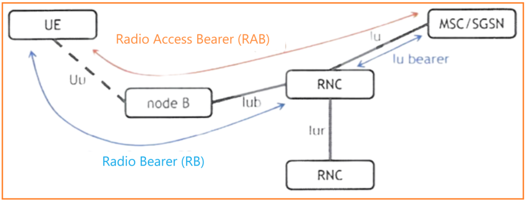
The figure provides more details on how the UMTS user plane operates.
Radio Access Bearer (RAB): In connected mode, a RAB is used to transport user data between the user equipment (UE) and the MSC (Mobile Switching Center) or SGSN (Serving GPRS Support Node). Each service type has its own RAB. For example, a voice call will use one RAB, while a simultaneous packet-switched (PS) data download will use another RAB. In idle mode, there is no RAB available.
Radio Bearer (RB): A Radio Bearer is used to transport user data between the UE and the RNC (Radio Network Controller). The Radio Bearer is a part of the Radio Access Bearer. The number of Radio Bearers used depends on the service. For voice calls, three Radio Bearers are used, while for other services, only one Radio Bearer is needed.
Iu Bearer: The Iu bearer is used to transport user data between the RNC and the MSC/SGSN.
Control/user plane flow during soft handover.

The figure explains the control plane and user plane flow during soft handover in a UMTS network. During a soft handover, the user equipment (UE) is in connected mode and maintains several simultaneous radio links to cells belonging to different Node Bs. This process involves multiple Radio Network Controllers (RNCs).
Soft Handover: In a soft handover, the UE connects to multiple cells, which may belong to different Node Bs.
RNC Roles:
- Serving RNC (SRNC): The master RNC that maintains the primary connection with the core network.
- Drift RNCs: The other RNCs involved in the soft handover, which assist the SRNC.
Control Plane and User Plane Flow:
- Both control plane and user plane data flow between the UE and the MSC/SGSN through the SRNC.
- Even though there is only one logical RRC (Radio Resource Control) connection between the UE and the SRNC, the RRC messages and user data travel over multiple radio links in a soft handover.
Advantages of Soft Handover:
- Redundancy: Multiple radio links ensure that if one link fails, others can maintain the connection.
- Soft Handover Gain: This redundancy helps lower the transmit power needed for both uplink and downlink, improving the overall connection quality and reducing interference.
Control Plane vs. User Plane Bit Pipe.
- Control plane bit pipe (RRC Connection):
- Signalling transport (RRC, NAS).
- Typically 4 sRBs setup during RRC Connection Setup procedure.
- User plane bit pipe:
- Transport of user data.
- 1or 3 RBs setup during RB Setup procedure.

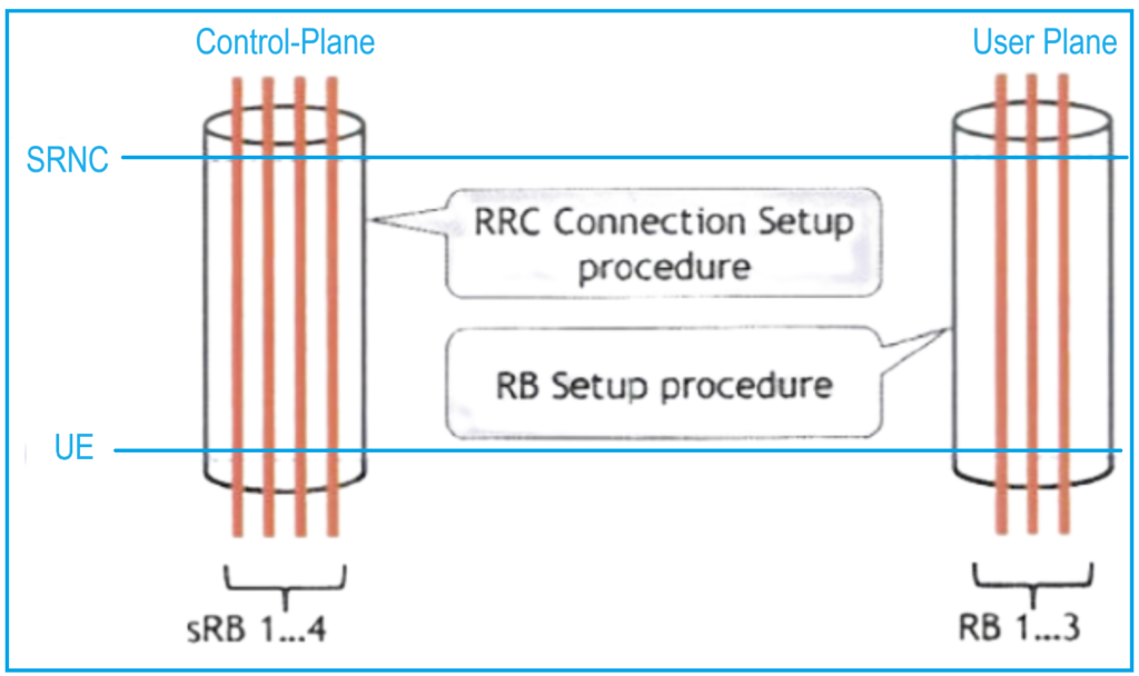
In a UMTS network, both the control plane and user plane require the transport of information: signaling and user data. The figure shows the “bit pipes” used to transport this information between the user equipment (UE) and the Serving RNC (SRNC).
Control Plane:
- RRC Connection: This is the bit pipe used for transporting signaling information (RRC and NAS messages) between the UE and the SRNC.
- Setup Procedure: The RRC connection is established through the RRC Connection Setup procedure, which will be discussed later. Typically, four signaling Radio Bearers are set up during this procedure.
User Plane:
- User Plane Bit Pipe: This is set up during the Radio Bearer Setup procedure and is used for transporting user data between the UE and the SRNC.
- Radio Bearers: Depending on the service, one or three Radio Bearers are established during this procedure. For a voice call, three Radio Bearers are used, while other services typically use one Radio Bearer.
Read Also: Counters & Statistics of 3G Air Interface Signalling.