Diagnostic with Fieldbus

I already have enough to do. Why should I make the added effort to use diagnostics? By enabling you to …

Read more

Foundation Fieldbus Control Design

This article is about Foundation Fieldbus Control design of Instrumentation and Control Engineering. Control Design of Foundation Fieldbus One of …

Read more

Fieldbus Cable and Segment Check Procedure

This article is about Fieldbus Cable and Segment Check Procedure and focusing to the engineers, technicians and supervisors. You will find lot of documents related to this article. Just navigate our website  www.paktechpoint.com  and find more articles. Please! Do not forget to subscribe our You tube channel also. Thanks in Advance.

PLEASE SUBSCRIBE OUR PAKTECHPOINT YOUTUBE CHANNEL

Fieldbus Cable and Segment Check Procedure

This document is prepared to understand and to detail about Fieldbus segment wiring check, segment diagnostics check and preparation of FF device for loop check. Fieldbus segment wiring check and commissioning is done in 3 parts in the following sequence
a. FF Cable Check.
b. Commissioning FF devices (Preparation for loop check).
c. Segment diagnostics check.

FF CABLE CHECK

As installation of transmitters will be based on construction status (equipment, piping etc), FF cable check will be done in 2 parts
Part 1 : FF cable check for Trunk cable (with transmitters may or may not be connected)
Part 2 : FF cable check for complete segment after all devices (transmitters/valves) of segment are connected. (This check is only for shield cable check)
If all devices in the segment are installed before part 1 check then part 2 check will not be required.

FF FIELD CABLE TEST PROCEDURE

TOOLS REQUIRED
1. Digital Multi-meter with resistance, DC voltage and capacitance measurement capability
2. Small screwdriver

FIELDBUS TERMINATOR

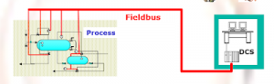
There are 2 FF terminators installed on the segment. One at the FF power supply (power hub) in DCS system cabinet and other at the Segment Protector in Level 2 junction box. Terminator at FF power supply in DCS system cabinet
FIELDBUS TERMINATOR
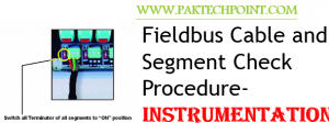
Terminator at Segment protector in Level 2 Junction Box


FIELDBUS TERMINATOR

PROCEDURE

PART 1 : FF CABLE CHECK FOR TRUNK CABLE FROM DCS CABINET TO LEVEL 2 JUNCTION BOX
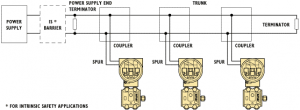
Figure below shows the connections of FF segment from DCS cabinet to Transmitter and details about the FF cable checks


1. Ensure that the Trunk cable wiring is properly terminated at DCS System cabinet and at Level1 and Level 2 Junction Box. Spur cables from Level 2 junction box to FF devices (transmitters/DVCs) may or may not be connected.
2. Ensure all all green connectors in Level 2 junction box (Segment Protector) closed.
3. Ensure Terminator at Power hub and at Segment protector is ‘ON’
4. Remove the fieldbus segment cable (+,-, and shield) by opening knife edge terminals at the DCS system cabinet side and measure the resistance and capacitance as per form below
Step 1: Resistance Check
Measure resistance from the:                                                                  Expected Result
+ signal conductor to – signal conductor                                             > 50 K Ohm
+ signal conductor to drain/shield conductor Open Circuit          >20 M Ohm
– signal conductor to drain/shield conductor Open Circuit           >20 M Ohm
+ signal conductor to shield ground bar Open Circuit                    >20 M Ohm
– signal conductor to shield ground bar Open Circuit                     >20 M Ohm
Shield conductor to safety earth bar Open Circuit                          >20 M Ohm (Note 1)
Step 2: Capacitance Check
Measure the capacitance at the terminal block in DCS system cabinet coming in from the field.
Measure capacitance from the:                                                     Expected Result
+ signal conductor to – signal conductor                         1 micro F (0.80 to 1.2 micro F acceptable)
+ signal conductor to drain/shield conductor                          < 300nF
– signal conductor to drain/shield conductor                           < 300nF
+ signal conductor to shield ground bar                                     < 300nF
– signal conductor to shield ground bar                                      < 300nF
Note 1: Main Shield cable from Shield bus bar in DCS System cabinet to Earthling cabinet is removed for this check
Note2: Capacitance value will change due to the capacitor charging in the termination RC circuit and the capacitance in the fieldbus cables.
Note3: A reading of <0.5 micro F indicates no terminator on the segment. A reading of a nominal 2 micro F indicates a second terminator on the segment. The acceptable values assume that the power supply terminator is used as the second terminator and only one additional terminator is connected in the field. Otherwise, the expected result would be 2 micro F
Note4: An actual reading that is much greater or varies in a capacitor-charging manner to a high capacitance value (>1 micro F) indicates a poor quality noisy ground on the shield ground bar. Be sure to correct this grounding problem to prevent communication errors on the fieldbus segment. A reading of 300 nF indicates noise on the ground system.
Complete the Fieldbus cable Checkout Form as per form in appendix A.

Read more

Foundation Fieldbus Overview

This article is about Foundation Fieldbus Overview and focusing to the engineers, technicians and supervisors. You will find lot of documents …

Read more

Foundation Fieldbus Applications

This article is about Foundation Fieldbus Applications and focusing to the engineers, technicians and supervisors. You will find lot of documents related to this article. Just navigate our website  www.paktechpoint.com  and find more articles. Please! Do not forget to subscribe our You tube channel also. Thanks in Advance.

PLEASE SUBSCRIBE OUR PAKTECHPOINT YOUTUBE CHANNEL

Foundation Fieldbus Applications

Fieldbus is both a Powerful Communications Protocol and an Enabling Technology.
Foundation Fieldbus-based Distributed Field Interfaces use the same function blocks as Fieldbus instruments. Only one software program is needed to configure every part of the system.

New Technology for Industry :

Most enterprises realise that recent developments in information and control technology, mathematical modelling, and advanced control algorithms are becoming available to the process industries. Most of these processes are characterised by highly complex, non-linear physicochemical phenomena. New technology approaches like adaptive control, advanced control strategies and fieldbus are being used to improve control and productivity performance.
Therefore production, quality, and safety gains are realised by obtaining more data from the field. Investments made on this area have produced paybacks in as little as six months in many cases.
Foundation Fieldbus-based Distributed Field Interfaces use the same function blocks as fieldbus instruments, the same PID block, the same AI block and so on. This means that only one software programme is needed to configure every part
of the system – transmitters, positioners and controllers – all in the same language. Thus the problem of linking Fieldbus blocks to proprietary languages is eliminated.
FCS configuration software can put the PID block either in a transmitter, positioner, or controller by simply dragging and dropping. An analogue input looks the same if it is in a pressure transmitter or a 4-20 mA input module in the I/O subsystem. This makes the system easier to use because you only need to install one set of hardware and learn one software programme.

Read more

Foundation Fieldbus Technology

This article is about Foundation Fieldbus Technology and focusing to the engineers, technicians and supervisors. You will find lot of documents related to this article. Just navigate our website  www.paktechpoint.com  and find more articles. Please! Do not forget to subscribe our You tube channel also. Thanks in Advance.

PLEASE SUBSCRIBE OUR PAKTECHPOINT YOUTUBE CHANNEL

Foundation Fieldbus Technology

All devices on a bus must use the same options for media, connection and transmission rate.
However, bus or non-bus powered devices may be mixed, as well as intrinsically safe or non-intrinsically safe ones.

Fieldbus Physical Layer

Closed loop control with performance like a 4-20 mA system, and variable speed drives require high data transmission speed. Since higher speed means higher power consumption, it then clashes with the need for intrinsic safety in some applications. Therefore one moderately high communication speed was selected, and other faster non-intrinsically safe options where also made available, catering to all applications. The system was designed to have a minimum of communication overhead to meet control requirements even with the low speed option.
There are several combinations for the physical layer, each with their relative merits. All devices on a bus must use the same options for media, connection and transmission rate. However, bus or non-bus powered devices may be mixed, as well as intrinsically safe or non-intrinsically safe ones.Physical media options:
•Wire
•Fiber optics (pending)
•Radio (pending)
Transmission rate options:
•31.25 kbit/s
•1 Mbit/s
•2.5 Mbit/s

Fieldbus Topology –  BUS

The wire media uses electrical signals on a normal twisted pair wire, and is already approved as an IEC/ISA standard
Fieldbus Topology -  BUS
The wire media uses electrical signals on a normal twisted pair wire, and is already approved as an IEC/ISA
standard since 1992.The maximum distance allowed between two devices on wire media depends on the transmission rate selected.
•31.25 kbit/s: 1,900 m
•1 Mbit/s (voltage mode): 750m
•1 Mbit/s (current mode): 750m
•2.5 Mbit/s: 500m

The device must isolate the communication hardware, Media Attachment Unit (MAU), from ground to avoid electrical ground loops when devices are multidropped.

Read more

Foundation Fieldbus OSI Model Versus OSI Model

This article is about Foundation Fieldbus OSI Model Versus OSI Model and focusing to the engineers, technicians and supervisors. You will find lot of documents related to this article. Just navigate our website  www.paktechpoint.com  and find more articles. Please! Do not forget to subscribe our You tube channel also. Thanks in Advance.

PLEASE SUBSCRIBE OUR PAKTECHPOINT YOUTUBE CHANNEL

Foundation Fieldbus OSI Model Versus OSI Model

How Fieldbus Works ?

There are two major parts to the Fieldbus system architecture: interconnection and application. Interconnection
refers to the passing of data from one device to another, may it be a field device, operator console or a configurator. This is the communication protocol part of Fieldbus. The application is the automation function the system performs. By standardizing part of the application, Fieldbus has gone further than any other communication standard, ensuring interoperability between conforming products.

Interconnection

It refers to the passing of data from one device to another, may it be a field device, operator console or a configurator.

Application

It is the automation function the system performs.

OSI  Model

The OSI reference model is an internationally recognized standard for network architecture on which open networks are based.
OSI  Model fieldbus


OSI  Model fieldbus
The layers are piled on top of each other and are together called the protocol  stack.  A layer only interfaces with layers immediately above and below in the stack.

OSI Model :

The OSI reference model is an internationally recognized standard for network architecture on which open networks are based. The standard is developed as a model for telecommunications on all levels. All the functions (facilities such as addressing, error checking and encoding/decoding) of a network have been grouped into logical sets called layers, altogether seven.
The layers are piled on top of each other and are together called the protocol stack. A layer only interfaces with
layers immediately above and below in the stack. The stack interfaces upwards to the application, and downwards to the transmission media.
 The part of the whole application performed by the system that is performed in a device is called the application
process (AP). The AP consists of two parts, one user portion, which is the functionality, and one communication portion. In Fieldbus the user portion is the actual device function, such as measurement or control (function blocks), or the user
interface.

Read more

Introduction to Foundation Fieldbus

Introduction of Micro Processor based Smart Sensors for Process Instrumentation. (1980) Introduction of  Centralized Computers for Process Instrumentation. (1970) Electronic Analog …

Read more

error: Content is Protected.