
Junction Box Requirements for Foundation Fieldbus
There are following requirements.
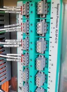
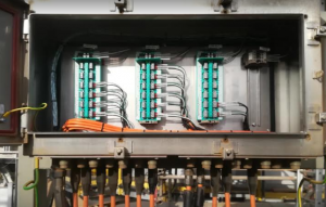
All trunk and spur connections in the field junction boxes, including pass through trunk pairs without spurs, shall be terminated on wiring-blocks specifically made for FOUNDATION™ Fieldbus networks.
Each FF field junction box shall be sized according to the number of segment trunk cables and devices that are connected through it. The maximum JB size allowable including installed spares shall provide termination blocks for the connection of three segments with 12 spurs on each. There shall be 20% installed spare device capacity in each Junction Box i.e. sufficient free connection points in the termination blocks to meet this requirement.
The ‘wiring block’ shall meet the following requirements:
- Two (2) dedicated connections for the fieldbus homerun/trunk cable.
- Trunk connections shall be non-sparking (no arcing) i.e., Ex nA.
- Integral short circuit protector for spur connections, maximum current to spur shall be no more than 60 mA.
- Spur connections shall be rated nonincendive (energy limited), i.e., Ex nL and shall have ‘live disconnect’ capability (including junction boxes).
- Pluggable (removable) ‘trunk’ and ‘spur’ connectors with retaining screws.
- LED indicator for each spur connection indicating when a spur is shorted and is in overcurrent mode.
- LED to indicate when bus power is available.
- Segment wiring block shall be CENELEC (ATEX) Ex nA[L]; Class 1, Zone 2, Gas Group IIC.
- Wire capacity: 12-24 AWG.
- Temperature range -45 to 70 deg C.
- DIN rail mounting.
- Available in four (4) spur and eight (8) spur configuration.
- A warning label must be prominently affixed on the junction box door (inside) stating the following: (red lettering with white background) “WARNING: Explosion Hazard – Do not connect or disconnect the ‘trunk connections’ on the wiring-block unless power has been switched off or the area is known to be non-hazardous.”
- An information label must be prominently affixed on the junction box door (inside) stating the following: (black lettering with white background) “The spur connections may be connected or disconnected while the circuit is live, i.e., you may connect or disconnect the spur on the wiring-block or at the device without sniffing the area for combustible gasses.”
- The wiring-blocks shall be mounted vertically in the field junction box.
- The DIN rail(s) in the junction box shall be designed with enough spare length to allow the future addition of one 8-spur or larger wiring-block.
- Junction Boxes shall contain only FF signal wiring.
- The junction box shall be a single door IP65 box.