RRC Setup Success Rate (CU)
The RRC connection setup process in 5G networks, as described in 3GPP TS 38.331, starts when the UE (User Equipment) triggers the setup for various reasons. The upper layers of the network determine the reason for the RRC connection setup. If the reason is related to signaling (mo-signaling), it’s for signaling purposes; other reasons relate to services.
The gNodeB (base station) tracks this process as a KPI (Key Performance Indicator). Here’s how it works:
- Every time the gNodeB receives an
RRCSetupRequestmessage from the UE (like at Point A in the diagram), it counts this as one RRC connection setup attempt. - If the setup is successful (shown at Point C), the gNodeB counts this as a successful RRC connection setup.
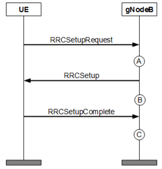
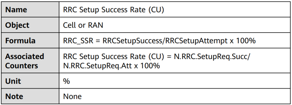
The RRC Setup Success Rate (CU) KPI is defined in below Table.
RRC Setup Success Rate (CU, Inactive).
When the RRC_INACTIVE_SWITCH option is enabled, and a UE (User Equipment) stops transmitting data for a while, it moves from the RRC_CONNECTED state to the RRC_INACTIVE state, rather than going to RRC_IDLE. This change reduces the number of RRC connection setup attempts and successful setups, impacting the overall success rate of RRC connection setups and Quality of Service (QoS) flow setups.
From the UE’s viewpoint, transitioning from RRC_INACTIVE back to RRC_CONNECTED is similar to starting a new RRC connection setup. Therefore, these connection resumes are counted in the KPI formula.
Triggering the Process:
- The RRC connection setup or resume process can be triggered by various reasons (or causes), which are determined by the upper layers of the network.
- When the cause is related to signaling (
mo-signaling), it’s for signaling purposes. Other causes are related to service needs.
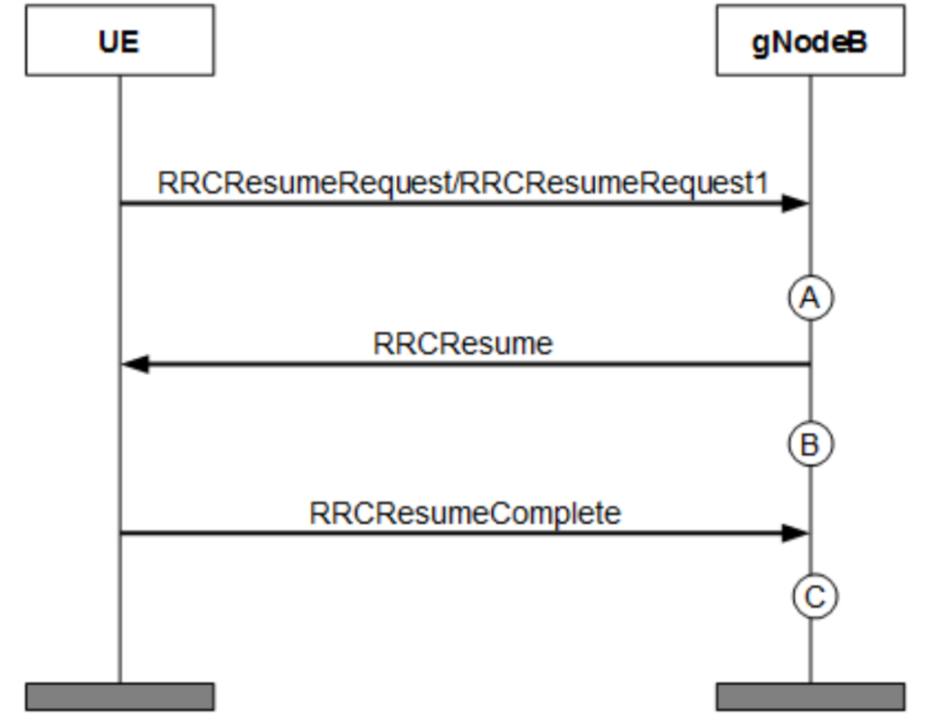
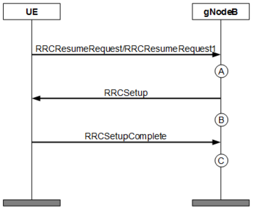
KPI Calculation:
- Setup Attempts: Each time the gNodeB receives an
RRCSetupRequestorRRCResumeRequestfrom the UE, it counts as an attempt. - Successful Setups: If the setup or resume is successful, it is counted as a successful attempt.
The RRC Setup Success Rate (CU, Inactive) KPI is defined in Table below.
| Name | RRC Setup Success Rate (CU, Inactive) |
| Object | Cell or RAN |
| Formula | RRC_SSR = RRCSetupSuccess/RRCSetupAttempt x 100% |
| Associated Counters | RRC Setup Success Rate (CU, Inactive) = (N.RRC.SetupReq.Succ + N.RRC.ResumeReq.Succ)/(N.RRC.SetupReq.Att + N.RRC.ResumeReq.Att) x 100% |
| Unit | % |
| Note | The KPI formula for the RRC_INACTIVE state applies to scenarios with the inactive switch turned on or turned off. It can be used as a common formula. |
RRC Setup Success Rate (Service) (CU)
The RRC Setup Success Rate (Service) is a KPI that measures how successfully a network establishes RRC (Radio Resource Control) connections specifically for service-related purposes.
Cause of Setup:
- According to the 3GPP TS 38.331 standard, the RRC connection setup process can be triggered by different causes, determined by the upper layers of the network.
- If the cause is related to signaling, it’s categorized as
mo-signaling. However, if the cause is related to services (like starting a data session or voice call), it’s considered a service-related setup.
How the KPI is Calculated:
- Setup Attempts: Every time the gNodeB (the network base station) receives an
RRCSetupRequestfrom the UE (User Equipment) for a service, it counts this as one setup attempt. - Successful Setups: If the connection is successfully established, it is recorded as a successful setup.

The RRC Setup Success Rate (Service) KPI is defined in Table below.
| Name | RRC Setup Success Rate (Service) (CU) |
| Object | Cell or RAN |
| Formula | RRC_SSRservice = RRCSetupSuccessservice/RRCSetupAttemptservice x 100% |
| Associated Counters | RRC Setup Success Rate (Service) (CU) = (N.RRC.SetupReq.Succ.Emc + N.RRC.SetupReq.Succ.HighPri + N.RRC.SetupReq.Succ.Mt + N.RRC.SetupReq.Succ.MoData + N.RRC.SetupReq.Succ.MoVoiceCall + N.RRC.SetupReq.Succ.MpsPri + N.RRC.SetupReq.Succ.MoSms + N.RRC.SetupReq.Succ.MoVideoCall)/(N.RRC.SetupReq.Att.Emc + N.RRC.SetupReq.Att.HighPri + N.RRC.SetupReq.Att.Mt + N.RRC.SetupReq.Att.MoData + N.RRC.SetupReq.Att.MoVoiceCall + N.RRC.SetupReq.Att.MpsPri + N.RRC.SetupReq.Att.MoSms + N.RRC.SetupReq.Att.MoVideoCall) x 100% |
| Unit | % |
| Note | None |
RRC Setup Success Rate (Service) (CU, Inactive)
The RRC Setup Success Rate (Service) (CU, Inactive) is a KPI that measures the success rate of establishing or resuming RRC connections for service-related activities, especially when a UE (User Equipment) transitions between different states in a 5G network.
RRC_INACTIVE_SWITCH Option:
- When this option is enabled, if a UE is inactive (not transmitting data) for a certain period, it moves from the
RRC_CONNECTEDstate to theRRC_INACTIVEstate, instead of going intoRRC_IDLE. This reduces the number of RRC connection setups and resumes, impacting the overall success rates for these processes.
RRC Connection Resume:
- From the UE’s perspective, resuming a connection from
RRC_INACTIVEtoRRC_CONNECTEDis treated similarly to setting up a new RRC connection. This process is included in the KPI calculation.
KPI Calculation:
- Connection Setup Attempts: Each time the gNodeB (network base station) receives an
RRCSetupRequestfrom a UE for a service-related reason, it counts as an attempt. - Connection Resume Attempts: Similarly, when a UE in
RRC_INACTIVEstate sends anRRCResumeRequest, it’s counted as a resume attempt. - Successes: Successful setups and resumes are recorded each time the connection is established or resumed correctly.


The RRC Setup Success Rate (Service) (CU, Inactive) KPI is defined in Table below.
| Name | RRC Setup Success Rate (Service) (CU, Inactive) |
| Object | Cell / Radio Network |
| Formula | RRC_SSRservice = RRCSetupSuccessservice/RRCSetupAttemptservice × 100% |
| Associated Counters | RRC Setup Success Rate (Service) (CU, Inactive) = (N.RRC.SetupReq.Succ.Emc + N.RRC.SetupReq.Succ.HighPri + N.RRC.SetupReq.Succ.Mt + N.RRC.SetupReq.Succ.MoData + N.RRC.SetupReq.Succ.MoVoiceCall + N.RRC.SetupReq.Succ.MpsPri + N.RRC.SetupReq.Succ.MoSms + N.RRC.SetupReq.Succ.MoVideoCall + N.RRC.ResumeReq.Succ.Emc + N.RRC.ResumeReq.Succ.HighPri + N.RRC.ResumeReq.Succ.Mt + N.RRC.ResumeReq.Succ.MoData + N.RRC.ResumeReq.Succ.MoVoiceCall + N.RRC.ResumeReq.Succ.MpsPri + N.RRC.ResumeReq.Succ.MoSms + N.RRC.ResumeReq.Succ.MoVideoCall)/(N.RRC.SetupReq.Att.Emc + N.RRC.SetupReq.Att.HighPri + N.RRC.SetupReq.Att.Mt + N.RRC.SetupReq.Att.MoData + N.RRC.SetupReq.Att.MoVoiceCall + N.RRC.SetupReq.Att.MpsPri + N.RRC.SetupReq.Att.MoSms + N.RRC.SetupReq.Att.MoVideoCall + N.RRC.ResumeReq.Att.Emc + N.RRC.ResumeReq.Att.HighPri + N.RRC.ResumeReq.Att.Mt + N.RRC.ResumeReq.Att.MoData + N.RRC.ResumeReq.Att.MoVoiceCall + N.RRC.ResumeReq.Att.MpsPri + N.RRC.ResumeReq.Att.MoSms + N.RRC.ResumeReq.Att.MoVideoCall) x 100% |
| Unit | % |
| Note | The KPI formula for the RRC_INACTIVE state applies to scenarios with the inactive switch turned on or turned off. It can be used as a common formula. |
RRC Setup Success Rate (Signaling) (CU)
The RRC Setup Success Rate for signaling (mo-signaling) is a KPI that measures how successfully the network establishes RRC connections for signaling purposes. This KPI is calculated by counting the number of times a UE attempts to set up an RRC connection for signaling (incremented at point A) and the number of successful setups (incremented at point C). It helps evaluate the efficiency of signaling-related RRC connections within a cell or across the entire network.

The RRC Setup Success Rate (Signaling) KPI is defined in below Table.
| Name | RRC Setup Success Rate (Signaling) (CU) |
| Object | Cell or RAN |
| Formula | RRC_SSRsignaling = RRCSetupSuccesssignaling/ RRCSetupAttemptsignaling x 100% |
| Associated Counters | RRC Setup Success Rate (Signaling) (CU) = N.RRC.SetupReq.Succ.MoSig/N.RRC.SetupReq.Att.MoSig x 100% |
| Unit | % |
| Note | None |
RRC Setup Success Rate (Signaling) (CU, Inactive)
The RRC Setup Success Rate for signaling (mo-signaling) in the context of the RRC_INACTIVE state is a KPI that evaluates how effectively signaling-related RRC connections are established in a network. When the RRC_INACTIVE_SWITCH option is enabled, a UE that stops data transmission moves from the RRC_CONNECTED state to the RRC_INACTIVE state instead of RRC_IDLE, reducing the number of RRC connection attempts and successes. This impacts the RRC connection setup success rate and the QoS flow setup success rate.
For UEs in the RRC_INACTIVE state, resuming an RRC connection to the RRC_CONNECTED state is treated similarly to initiating an RRC connection setup or QoS flow setup. Thus, the number of RRC connection resumes is also included in the KPI calculation.
As specified in 3GPP TS 38.331, the RRC connection setup or resume procedure can be triggered by various causes, determined by the upper layer of the protocol stack. The setup or resume procedure for mo-signaling relates to signaling, while other causes relate to services.
This KPI is calculated when a UE attempts an RRC connection setup or resume for signaling purposes. Specifically:
- At point A in Figure below, the number of signaling-related RRC connection setup attempts is incremented each time the gNodeB receives an RRCSetupRequest from the UE.
- At point C, the number of successful setups is incremented.

- Similarly, at point A in Figure below, the number of signaling-related RRC connection resume attempts is incremented with each RRCResumeRequest received.
- At point C, the number of successful resume procedures is incremented.

The RRC Setup Success Rate (Signaling) (CU, Inactive) KPI is defined in Table below.
| Name | RRC Setup Success Rate (Signaling) (CU, Inactive) |
| Object | Cell or RAN |
| Formula | RRC_SSRsignaling = RRCSetupSuccesssignaling/ RRCSetupAttemptsignaling x 100% |
| Associated Counters | RRC Setup Success Rate (Signaling) (CU, Inactive) = (N.RRC.SetupReq.Succ.MoSig + N.RRC.ResumeReq.Succ.MoSig)/ (N.RRC.SetupReq.Att.MoSig + N.RRC.ResumeReq.Att.MoSig) x 100% |
| Unit | % |
| Note | The KPI formula for the RRC_INACTIVE state applies to scenarios with the inactive switch turned on or turned off. It can be used as a common formula. |
NGSIG Connection Setup Success Rate (CU)
This KPI measures the success rate of signaling connection setups over the NG interface, which is critical for managing UE-related signaling connections between the gNodeB and the AMF.
Setup Attempts: Each time the gNodeB sends an INITIAL UE MESSAGE to the AMF or receives the first NG message from the AMF, the counter for NG signaling connection setup attempts is incremented. The INITIAL UE MESSAGE is the first message that the gNodeB sends to the AMF, containing the NAS configuration information for the UE. This message is essential for the AMF to establish NG signaling connections for UEs.
Successful Setups: When the gNodeB receives the first NG message from the AMF (such as an INITIAL CONTEXT SETUP REQUEST, DOWNLINK NAS TRANSPORT, or UE CONTEXT RELEASE COMMAND), the NG signaling connection is considered successfully established. The counter for successful NG signaling connection setups is then incremented.
Point A: Represents the increment of NG signaling connection setup attempts each time the gNodeB sends an INITIAL UE MESSAGE to the AMF.
Point B: Represents the increment of successful NG signaling connection setups when the gNodeB receives the first NG message from the AMF after sending the INITIAL UE MESSAGE.
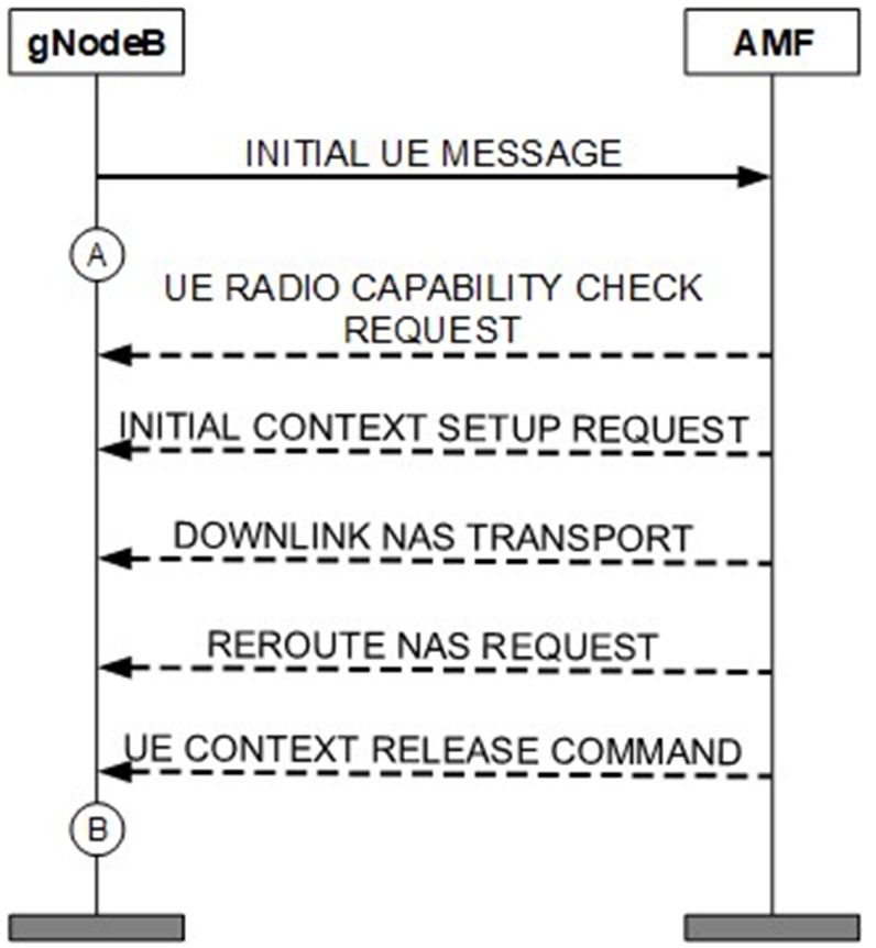
The NGSIG Connection Setup Success Rate KPI is defined in Table below.
| Name | NGSIG Connection Setup Success Rate (CU) |
| Object | Cell or RAN |
| Formula | NGSIG_SSR = NGSIGConnectionEstablishSuccess/ NGSIGConnectionEstablishAttempt x 100% |
| Associated Counters | NGSIG Connection Setup Success Rate (CU) = N.NGSig.ConnEst.Succ/N.NGSig.ConnEst.Att x 100% |
| Unit | % |
| Note | None |
QoS Flow Setup Success Rate (CU)
This KPI measures the success rate of Quality of Service (QoS) flow setups for all services within a cell. It involves tracking both the number of QoS flow setup attempts and the number of successful QoS flow setups.
QoS Flow Setup Attempts:
- Each time the gNodeB receives specific messages from the AMF such as an INITIAL CONTEXT SETUP REQUEST, PDU SESSION RESOURCE SETUP REQUEST, or PDU SESSION RESOURCE MODIFY REQUEST – the counter for QoS flow setup attempts is incremented.
- If these messages request the setup of multiple QoS flows, the counter is increased by the corresponding number of QoS flows.
Successful QoS Flow Setups:
- The counter for successful QoS flow setups is incremented each time the gNodeB sends a response to the AMF such as a PDU SESSION RESOURCE SETUP RESPONSE, INITIAL CONTEXT SETUP RESPONSE, or PDU SESSION RESOURCE MODIFY RESPONSE.
- If the response message confirms the successful setup of multiple QoS flows, the total number of successful setups is accumulated based on the count in the message.
Emergency Voice Fallback:
- When the gNodeB receives an INITIAL CONTEXT SETUP REQUEST from the AMF for an emergency voice fallback UE, the counter for QoS flow setup attempts in the cell is incremented.
- If multiple QoS flows are requested, the counter is increased by the number of setups triggered by the emergency voice fallback.
EPS Fallback:
- The counter for QoS flow setup attempts triggered by EPS fallback is incremented when the gNodeB receives a PDU SESSION RESOURCE MODIFY REQUEST from the AMF for an EPS fallback UE.
- Similar to other scenarios, if multiple QoS flows are requested, the counter is increased by the number of setups.
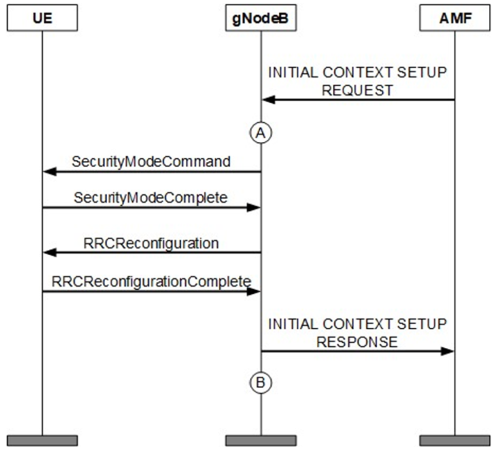
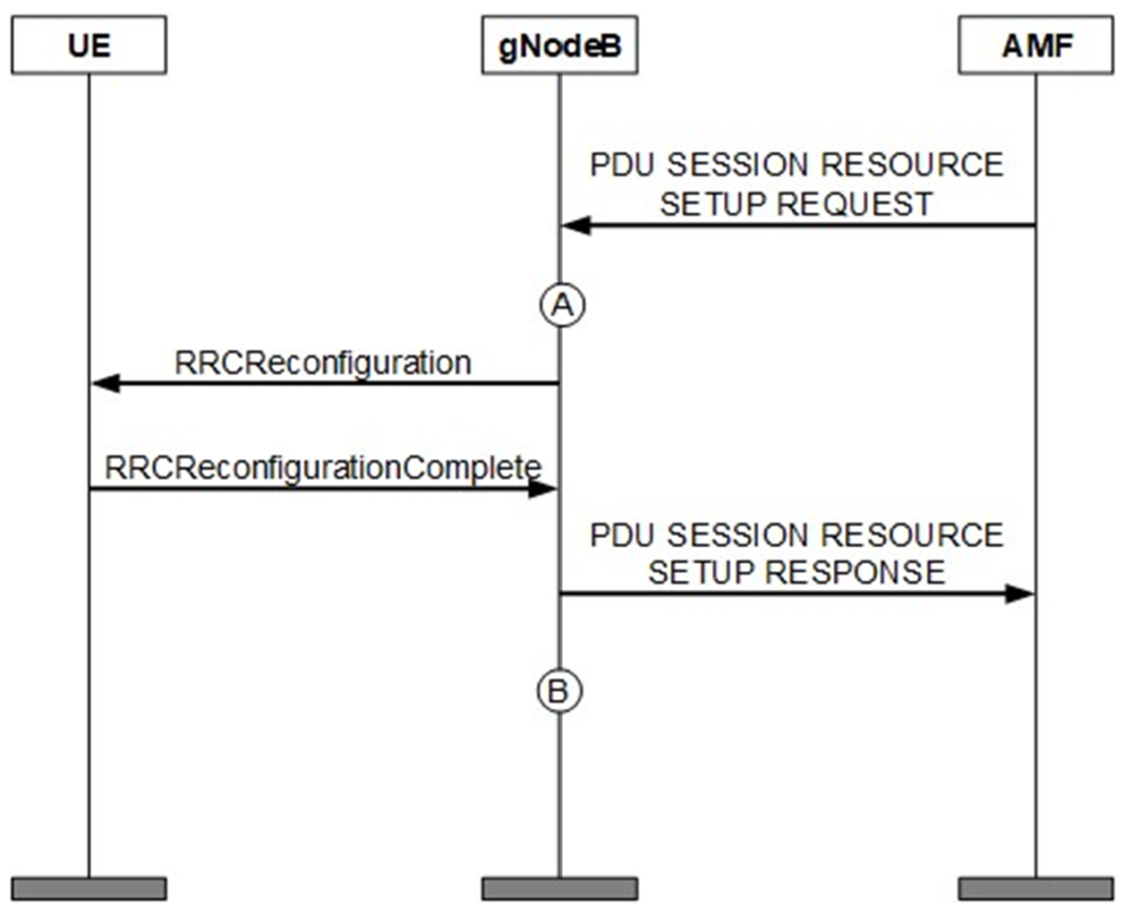
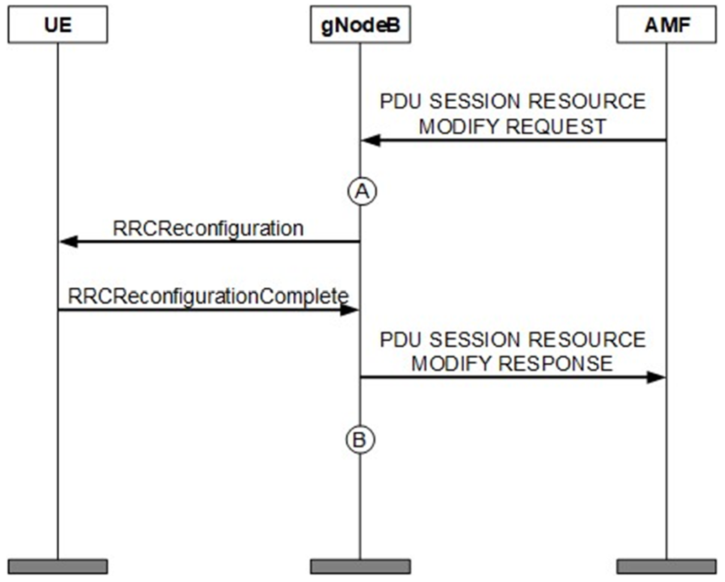
These counters are accumulated within the cell serving the UE and are crucial for evaluating the network’s ability to establish QoS flows efficiently across various scenarios.
Table below lists the definition of the QoS flow setup success rate of all services.
| Name | Qos Flow Setup Success Rate (CU) |
| Object | Cell or RAN |
| Formula | QoS Flow_SSR = QosFlowSetupSuccess/QosFlowSetupAttempt x 100% |
| Associated Counters | QoS Flow Setup Success Rate (CU) = N.QosFlow.Est.Succ/ (N.QosFlow.Est.Att – N.QosFlow.Est.Att.EPSFB – N.QosFlow.Est.Att.EmcFB) x 100% |
| Unit | % |
| Note | None |
QoS Flow Setup Success Rate (CU, Inactive)
The QoS Flow Setup Success Rate (CU) KPI measures the success rate of setting up QoS flows for all services in a 5G network. This KPI includes various counters such as the number of QoS flow setup attempts, the number of successful QoS flow setups, the number of QoS flow resume attempts when transitioning from RRC_INACTIVE to RRC_CONNECTED, and the number of successful QoS flow resumes.
When the RRC_INACTIVE_SWITCH option is enabled, if a UE is inactive for a period, it moves from the RRC_CONNECTED state to the RRC_INACTIVE state instead of the RRC_IDLE state. This transition affects the number of RRC connection setups and, subsequently, the QoS flow setup success rate.
To maintain accuracy, the KPI formula includes the number of QoS flow resumes from RRC_INACTIVE to RRC_CONNECTED. This is because, from the UE’s perspective, resuming the connection from RRC_INACTIVE is similar to setting up a new RRC connection and QoS flow.
Key points in calculating this KPI:
- Setup Attempts: Every time the gNodeB receives a message like INITIAL CONTEXT SETUP REQUEST, PDU SESSION RESOURCE SETUP REQUEST, or PDU SESSION RESOURCE MODIFY REQUEST, the QoS flow setup attempts are incremented. If the message involves multiple QoS flows, each flow setup attempt is counted.
- Successful Setups: When the gNodeB sends a response (like PDU SESSION RESOURCE SETUP RESPONSE), the number of successful QoS flow setups is recorded. If the response involves multiple QoS flows, all successful setups are counted.
- Resume Attempts: Each time the gNodeB sends an RRCResume message, it increments the number of QoS flow resume attempts. This counts all QoS flows that are being resumed.
- Successful Resumes: When the gNodeB receives an RRCResumeComplete message from the UE, or when it sends a UE CONTEXT RELEASE message, the number of successful QoS flow resumes is recorded.
Special cases include:
- Emergency Voice Fallback: The number of QoS flow setup attempts increases when the gNodeB receives an INITIAL CONTEXT SETUP REQUEST for an emergency voice fallback UE.
- EPS Fallback: The number of QoS flow setup attempts increases when the gNodeB receives a PDU SESSION RESOURCE MODIFY REQUEST for an EPS fallback UE.


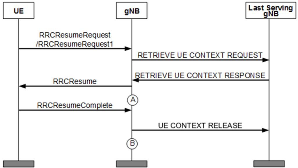
Table below lists the definition of the QoS flow setup success rate of all services.
| Name | QoS Flow Setup Success Rate (CU, Inactive) |
| Object | Cell or RAN |
| Formula | QoS Flow_SSR = QosFlowSetupSuccess/QosFlowSetupAttempt x 100% |
| Associated Counters | QoS Flow Setup Success Rate (CU, Inactive) = (N.QosFlow.Est.Succ + N.QosFlow.Resume.Succ)/ (N.QosFlow.Est.Att + N.QosFlow.Resume.Att – N.QosFlow.Est.Att.EPSFB – N.QosFlow.Est.Att.EmcFB) x 100% |
| Unit | % |
| Note | The KPI formula for the RRC_INACTIVE state applies to scenarios with the inactive switch turned on or turned off. It can be used as a common formula. |
QoS Flow Setup Success Rate (CU, VoNR)
The KPI for QoS Flow Setup Success Rate of VoNR (Voice over New Radio) services is specifically designed to assess how effectively the network establishes QoS flows for VoNR services. These services typically utilize a 5QI (5G QoS Identifier) value of 1, which corresponds to low-latency, high-reliability services essential for voice communication over the 5G network.
- QoS Flow Setup Attempts: This counter increments every time the gNodeB attempts to set up a QoS flow for a VoNR service. This setup attempt is recorded when the gNodeB receives relevant signaling messages like an INITIAL CONTEXT SETUP REQUEST, PDU SESSION RESOURCE SETUP REQUEST, or PDU SESSION RESOURCE MODIFY REQUEST from the AMF (Access and Mobility Management Function).
- Successful QoS Flow Setups: This counter tracks the number of successful QoS flow setups for VoNR services. A setup is considered successful when the gNodeB responds with a message such as PDU SESSION RESOURCE SETUP RESPONSE or INITIAL CONTEXT SETUP RESPONSE, indicating that the QoS flow has been successfully established for the VoNR service.
Activation of VoNR 5QI Measurement:
To specifically measure the success rate for VoNR services, the required VoNR 5QI measurement objects can be activated via the gNB5qiConfig.CounterObjSubscriptionInd parameter. This enables the tracking of QoS flow setups that are specifically tied to VoNR services, ensuring accurate KPI measurements.
KPI Calculation:
The VoNR QoS Flow Setup Success Rate is defined as the ratio of the number of successful QoS flow setups to the total number of QoS flow setup attempts for VoNR services. This KPI is crucial for evaluating the network’s ability to support high-quality voice services over 5G, ensuring that VoNR calls are reliably connected with the required QoS.
Table below would typically provide a detailed breakdown of how this KPI is calculated, including definitions, thresholds, and any additional parameters involved in measuring the setup success rate for VoNR services.
| Name | QoS Flow Setup Success Rate (CU, VoNR) |
| Object | Cell or RAN |
| Formula | QoS Flow_SSR = QosFlowSetupSuccess/QosFlowSetupAttempt x 100% |
| Associated Counters | QoS Flow Setup Success Rate (CU, VoNR) = N.QosFlow.Est.Succ.Cell5QI/(N.QosFlow.Est.Att.Cell5QI – N.QosFlow.Est.Att.Cell5QI.EPSFB – N.QosFlow.Est.Att.Cell5QI.EmcFB) x 100% |
| Unit | % |
| Note | None |
Call Setup Success Rate (CU)
This KPI is designed to evaluate the overall success rate of call setups across all services in the 5G network. It integrates the success rates of three critical processes:
- RRC Connection Setup Success Rate for Services: This measures how effectively RRC connections are established for services.
- NG Signaling Connection Setup Success Rate: This evaluates the success rate of establishing signaling connections over the NG interface between the gNodeB and the AMF.
- QoS Flow Setup Success Rate: This assesses the success rate of establishing the necessary QoS flows for different services.
The Call Setup Success Rate KPI is a composite metric, defined as the product of the following individual success rates:
- RRC Connection Setup Success Rate for Services
- NG Signaling Connection Setup Success Rate
- QoS Flow Setup Success Rate
This KPI provides a holistic measure of the network’s ability to successfully establish call setups, considering all necessary signaling and QoS components. Table below would detail the specific formula and components used to calculate this KPI.
| Name | Call Setup Success Rate (CU) |
| Object | Cell / Radio Network |
| Formula | CSSR = (RRCSetupSuccessservice/RRCSetupAttemptservice) x (NGSIGConnectionEstablishSuccess/NGSIGConnectionEstablish- Attempt) x (QosFlowSetupSuccess/QosFlowSetupAttempt) x 100% |
| Associated Counters | Call Setup Success Rate (CU) = ((N.RRC.SetupReq.Succ.Emc + N.RRC.SetupReq.Succ.HighPri + N.RRC.SetupReq.Succ.Mt + N.RRC.SetupReq.Succ.MoData + N.RRC.SetupReq.Succ.MoVoiceCall + N.RRC.SetupReq.Succ.MpsPri + N.RRC.SetupReq.Succ.MoSms + N.RRC.SetupReq.Succ.MoVideoCall)/(N.RRC.SetupReq.Att.Emc + N.RRC.SetupReq.Att.HighPri + N.RRC.SetupReq.Att.Mt + N.RRC.SetupReq.Att.MoData + N.RRC.SetupReq.Att.MoVoiceCall + N.RRC.SetupReq.Att.MpsPri + N.RRC.SetupReq.Att.MoSms + N.RRC.SetupReq.Att.MoVideoCall)) x (N.NGSig.ConnEst.Succ/ N.NGSig.ConnEst.Att) x (N.QosFlow.Est.Succ/(N.QosFlow.Est.Att – N.QosFlow.Est.Att.EPSFB – N.QosFlow.Est.Att.EmcFB)) x 100% |
| Unit | % |
| Note | None |
Call Setup Success Rate (CU, Inactive)
This variant of the Call Setup Success Rate KPI is applicable in scenarios where the RRC_INACTIVE state is utilized. It evaluates the call setup success rate for all services, considering both active and inactive states of the UE. This KPI includes:
- RRC Connection Setup Success Rate for Services (Inactive): Reflects the success rate of resuming RRC connections from the RRC_INACTIVE state to RRC_CONNECTED.
- NG Signaling Connection Setup Success Rate: Remains the same as in the active scenario.
- QoS Flow Setup Success Rate (Inactive): Measures the success rate of resuming or setting up QoS flows when the UE transitions from RRC_INACTIVE to RRC_CONNECTED.
Similar to the active scenario, this KPI is the product of the RRC Connection Setup Success Rate for Services (Inactive), NG Signaling Connection Setup Success Rate, and QoS Flow Setup Success Rate (Inactive). Table below would provide the specific calculation details, ensuring a comprehensive measure of the network’s performance in handling call setups, even when UEs transition from an inactive state.
| Name | Call Setup Success Rate (CU, Inactive) |
| Object | Cell or RAN |
| Formula | CSSR = (RRCSetupSuccessservice/RRCSetupAttemptservice) x (NGSIGConnectionEstablishSuccess/NGSIGConnectionEstablish- Attempt) x (QosFlowSetupSuccess/QosFlowSetupAttempt) x 100% |
| Associated Counters | Call Setup Success Rate (CU, Inactive) = ((N.RRC.SetupReq.Succ.Emc + N.RRC.SetupReq.Succ.HighPri + N.RRC.SetupReq.Succ.Mt + N.RRC.SetupReq.Succ.MoData + N.RRC.SetupReq.Succ.MoVoiceCall + N.RRC.SetupReq.Succ.MpsPri + N.RRC.SetupReq.Succ.MoSms + N.RRC.SetupReq.Succ.MoVideoCall +N.RRC.ResumeReq.Succ.Emc + N.RRC.ResumeReq.Succ.HighPri + N.RRC.ResumeReq.Succ.Mt + N.RRC.ResumeReq.Succ.MoData + N.RRC.ResumeReq.Succ.MoVoiceCall + N.RRC.ResumeReq.Succ.MpsPri + N.RRC.ResumeReq.Succ.MoSms + N.RRC.ResumeReq.Succ.MoVideoCall)/(N.RRC.SetupReq.Att.Emc + N.RRC.SetupReq.Att.HighPri + N.RRC.SetupReq.Att.Mt + N.RRC.SetupReq.Att.MoData + N.RRC.SetupReq.Att.MoVoiceCall + N.RRC.SetupReq.Att.MpsPri + N.RRC.SetupReq.Att.MoSms + N.RRC.SetupReq.Att.MoVideoCall + N.RRC.ResumeReq.Att.Emc + N.RRC.ResumeReq.Att.HighPri + N.RRC.ResumeReq.Att.Mt + N.RRC.ResumeReq.Att.MoData + N.RRC.ResumeReq.Att.MoVoiceCall + N.RRC.ResumeReq.Att.MpsPri + N.RRC.ResumeReq.Att.MoSms + N.RRC.ResumeReq.Att.MoVideoCall)) × (N.NGSig.ConnEst.Succ/ N.NGSig.ConnEst.Att) × (N.QosFlow.Est.Succ + N.QosFlow.Resume.Succ)/(N.QosFlow.Est.Att + N.QosFlow.Resume.Att – N.QosFlow.Est.Att.EPSFB – N.QosFlow.Est.Att.EmcFB) x 100% |
| Unit | % |
| Note | The KPI formula for the RRC_INACTIVE state applies to scenarios with the inactive switch turned on or turned off. It can be used as a common formula. |