The NR handover process involves several signaling messages exchanged between the UE (User Equipment), the source gNB (gNodeB), and the target gNB. This process ensures that the UE maintains continuous connectivity while moving from one cell to another.
1. Standalone (SA) Handover Signaling.
1. Standard Signaling for NR Handover.
When there is a handover issue, it’s crucial to analyze the background signaling to identify and locate the fault. The standard signaling flow for a handover process can be broken down into clear steps.

First, the source gNodeB receives a measurement report from the UE indicating that a handover is needed. The source gNodeB then decides to initiate the handover to the target gNodeB. To do this, the source gNodeB directly requests resources from the target gNodeB through the X2 interface. This step is crucial as it involves preparing the necessary resources at the target cell.
Once the target gNodeB has allocated the required resources, it sends an acknowledgment back to the source gNodeB. Following this, the source gNodeB notifies the UE to start the handover process to the target cell. This notification is done through a reconfiguration message sent over the air interface.
After the UE successfully completes the handover to the target cell, the target gNodeB informs the source gNodeB to release the radio resources of the source cell. This ensures that resources are efficiently managed and not wasted.
Additionally, any data that was not sent by the source gNodeB needs to be forwarded to the target gNodeB. This step is essential to ensure that there is no data loss during the handover process. Finally, the relationship between the user plane and the control plane nodes must be updated to reflect the new configuration, ensuring seamless connectivity and proper data flow.
2. Air-Interface Signaling During Foreground Test.
The following figures is about the signaling messages involved in the initial access and handover processes in a foreground test. These steps help analysis personnel locate faults based on the signaling flow.
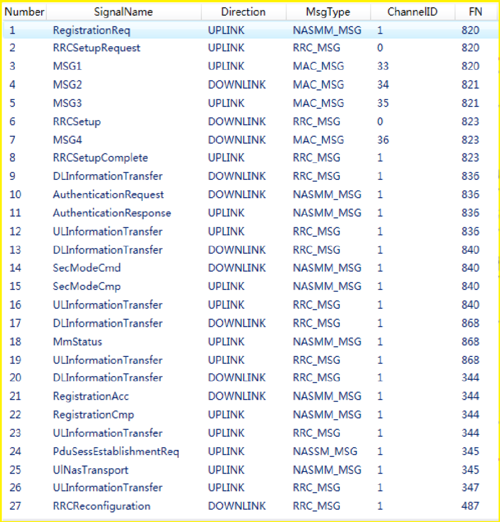

- Measurement and Control Message:
- Signaling Messages No. 31 and 32: The base station instructs the UE on which cells to measure and how to conduct these measurements.
- Measurement Report:
- Signaling Message No. 33: The UE reports the best measured cell back to the base station based on the instructed measurements.
- Handover Command:
- Signaling Messages No. 34, 35, and 36: The base station provides the UE with the access information for the target cell, notifying it to start the handover process.
- Non-contention-based Access:
- MSG1/MSG2 (Signaling Messages No. 38 and 39): These messages confirm that the UE has successfully accessed the target cell, indicating a successful handover. The handover is considered successful only if MSG2 is seen in the foreground test.
- New Measurement Control Message:
- Signaling Message No. 40: Sent from the target cell, this message instructs the UE on measurements for the next potential handover.
Additionally, the UE sends a reconfiguration complete message in advance, further confirming the successful handover. By following this sequence and observing the corresponding signaling messages, faults in the handover process can be accurately identified and addressed.
3. Key Signaling.
1. Measurement Control Message (RRC Reconfiguration):
The Measurement Control Message, sent via RRC Reconfiguration, directs the UE on which cells to measure. It includes configurations for neighbor cells that the UE should monitor.
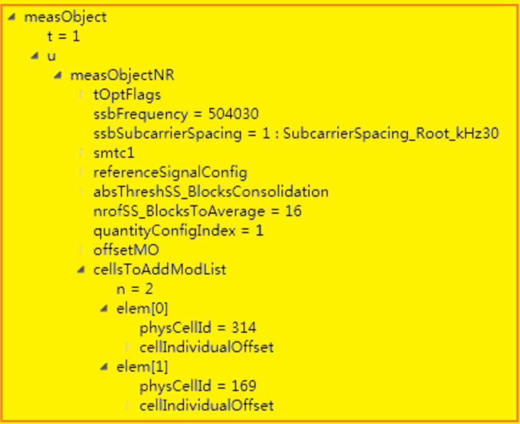
Additionally, it specifies the A3 event parameters used for handover, defining the thresholds that trigger the handover decision.
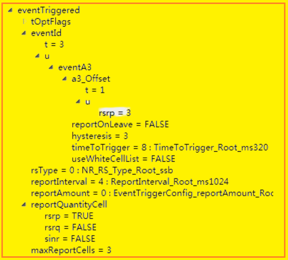
2. Measurement Report.
Following the instructions from the Measurement Control Message, the UE generates a Measurement Report. This report includes measurements of both the serving cell and any target cells that might be candidates for handover. It’s important to note that the UE’s measurement report may not always include all configured neighbor cells due to current network limitations, specifically the lack of support for neighbor cell self-optimization. This discrepancy can help identify instances where expected neighbor cells are not properly configured.
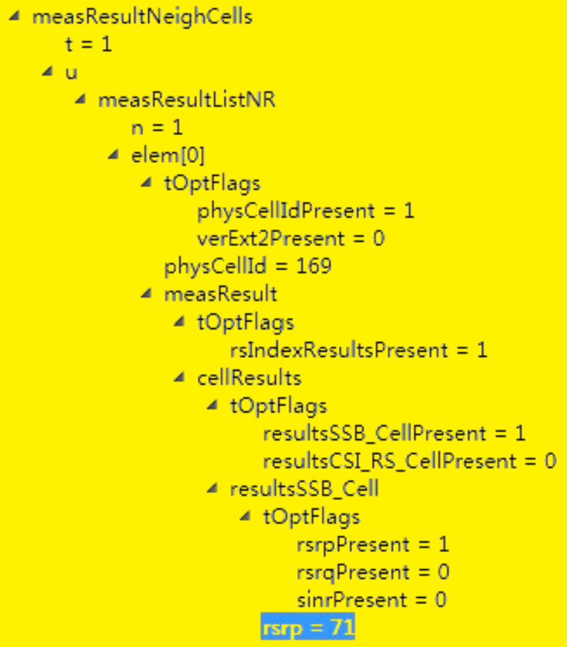

3. Handover Execution (RRC Reconfiguration)
During Handover Execution, also facilitated through RRC Reconfiguration, the UE receives access information for the target cell. This information allows the UE to transition to the target cell using a non-contention-based access method. This process ensures seamless continuity of service as the UE moves between cells, based on the measured parameters and handover criteria defined earlier in the Measurement Control Message.

2. Non-Standalone (NSA) Handover Signaling.
1. Standard Signaling.

Here’s a overview of the signaling process for Sn Addition in the NSA networking mode:
- X2 Connection Establishment: The MeNB establishes an X2 connection with the SgNB.
- UE Attachment and Service Setup: The UE is connected to the MeNB’s network (primary node) and the EPC (Evolved Packet Core), establishing a service bearer.
- NR Measurement Configuration: The MeNB sends NR measurement configurations to the UE, including B1 event thresholds.
- B1 Measurement Report: When the B1 event threshold is met, the UE sends a B1 measurement report to the MeNB.
- Sn Addition Request: Based on the B1 measurement report, the MeNB decides to add an SgNB. It sends an Sn Addition Request message to the SgNB, containing:
- E-RABs-ToBeAddedList.
- MeNBtoSeNBContainer (including SCG-ConfigInfo).
- SgNB Processing:
- The SgNB selects a PSCell candidate and performs admission control.
- If successful, the SgNB replies with an SgNB Addition Request Acknowledge message. If unsuccessful, it replies with an SgNB Addition Request Reject message.
- RRC Connection Reconfiguration: Upon receiving SgNB Addition Request Acknowledge, the MeNB sends an RRC Connection Reconfiguration message to the UE. This message includes SCG configuration details for the SgNB.
- UE Processing:
- The UE completes SCG configuration and responds with an RRC Connection Reconfiguration Complete message to the MeNB.
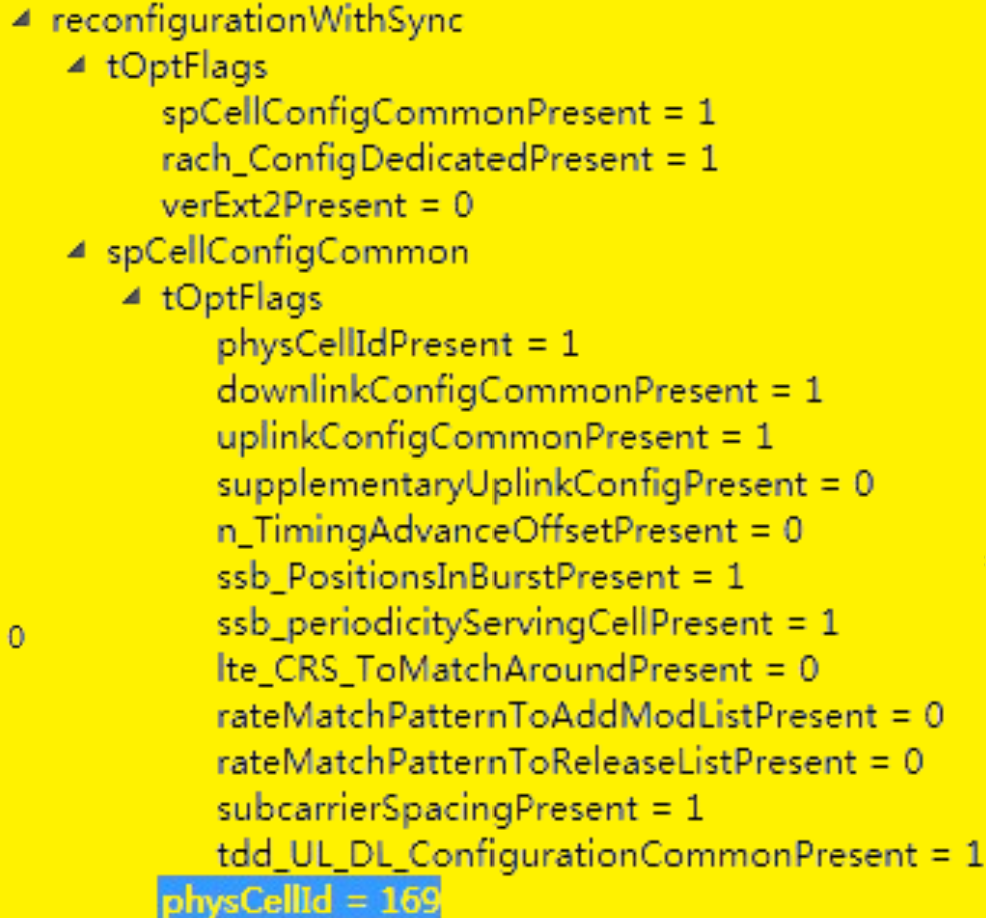
- The UE receives PSCell downlink signals, captures system broadcast MIB information, and configures based on ServingCellConfigCommon in the RRC message.
- UE Access to SgNB: The UE accesses the SgNB cell using either contention-based or non-contention-based access methods.
- Sn Reconfiguration Complete: After the UE completes RRC reconfiguration, the MeNB sends an Sn Reconfiguration Complete message to the SgNB, indicating successful UE air interface reconfiguration.
- Cross-PCE Scenario (Optional):
- If across different PCEs, the MeNB sends an SN Status Transfer message to the SgNB to transfer data and avoid service interruption.
- E-RAB Modification: Also in cross-PCE scenarios, the MeNB informs the EPC of downlink tunnel changes via an E-RAB Modification Indication message, awaiting confirmation.
- Measurement Reconfiguration: Post-SgNB addition, the PSCell at the SgNB sends a measurement reconfiguration message to the UE via SRB3, including A2 event thresholds.
This process ensures seamless addition of the SgNB in a non-standalone (NSA) architecture, maintaining service continuity and optimizing network performance based on UE measurements and handover decisions.
Standard Signaling of Handover in the NSA Networking Mode.
In the NSA (Non-Standalone) networking mode, the handover procedure involves additional steps compared to the SN (Standalone) networking mode.
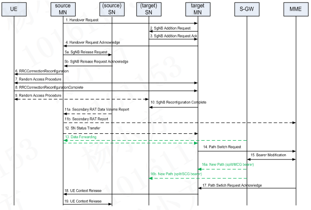
Here’s a the standard signaling process:
- Handover Request: When a handover is triggered, the source MN (Master Node) sends a handover request to the target MN, indicating that the UE (User Equipment) is to be handed over to the target cell.
- Target SN Addition: Upon receiving the handover request, the target MN initiates the addition of the target SN (Secondary Node) to which the UE will be handed over. This step ensures that the target cell is prepared to receive the UE.
- Acknowledgement and SN Release: After the target MN processes the handover request and confirms successful preparation (typically with an acknowledgement), the source MN proceeds to release the SN associated with the source cell. This release ensures that resources are efficiently managed between cells during the handover.
- Update of User and Control Plane: Following the successful addition of the target SN and release of the source SN, there’s an update in both the user plane (where data flows) and the control plane (where signaling and management occur). This update ensures that ongoing sessions and services are smoothly transitioned to the target cell.
- Data Forwarding: During this process, data that was not yet transmitted from the source SN is forwarded to the target SN through the MN. This step prevents service interruptions and maintains continuity as the UE moves between cells.
Signaling of Sn Release in the NSA Networking Mode.
In the NSA (Non-Standalone) networking mode, when a Secondary Node (SgNB) release is initiated, the signaling procedure unfolds as follows:
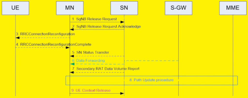
- SgNB Release Request: The MeNB (Master Node) sends an SgNB Release Request message to the SgNB through the X2 interface, signaling the start of the SgNB release procedure.
- SgNB Release Request Acknowledge: Upon receiving the SgNB Release Request, the SgNB responds with an SgNB Release Request Acknowledge message. This acknowledgement indicates that the SgNB acknowledges the release request and ceases sending service data over the NR (5G New Radio) air interface.
3/4. RRC Connection Reconfiguration: The MeNB then sends an RRC Connection Reconfiguration message to the UE (User Equipment), which includes the SCG-RELEASE Information Element (IE). This message informs the UE about the release of the Secondary Cell Group (SCG). The UE responds with an RRC Connection Reconfiguration Complete message, confirming the reception and processing of the release instruction.
5/6/7. Cross-PCE Scenario Data Transfer: In scenarios involving multiple Packet Core Entities (PCEs), data transfer may occur back from the SgNB to the MeNB to ensure continuity and avoid service interruption during the deactivation of dual-connectivity. This involves:
- The SgNB sending an SN Status Transfer message to the MeNB.
- Optionally, the SgNB sending a Secondary RAT (Radio Access Technology) Data Volume Report message to the MeNB, providing additional context on data usage.
- The MeNB may send an EPC E-RAB Modification Indication message to the EPC (Evolved Packet Core), notifying it of changes in downlink tunnel information. The EPC responds with an E-RAB Modification Confirmation message, confirming the update.
8. UE Context Release: The MeNB sends a Ue Context Release message to the SgNB, instructing it to release local resources associated with the SgNB. Upon receiving this message, the SgNB completes the release process, and any active bearer finally transitions back to the MeNB’s network.
This signaling sequence ensures that the release of the SgNB is managed smoothly, minimizing disruption to ongoing services and ensuring that resources are efficiently managed within the network.
2. Foreground Air Interface Signaling.
Signaling in the Window at the MN Side.

Dual-Connection Establishment.

Handover at the 4G Side, MN and SN Release.
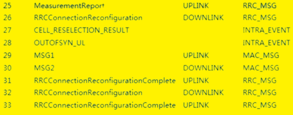
SN Addition of the Target Cell.

Signaling in the Window at the Sn Side.
Corresponding to SN Addition of the 4G Source Cell.

Corresponding to SN Addition of the Target Cell.

In the current handover solution for the NSA (Non-Standalone) networking mode, the relationship between the Master Node (MN) and the Secondary Node (SN) is exclusive. Here’s a breakdown of the process:
- Exclusive Correspondence: Each MN corresponds to a specific SN. This means that the SN is tied to the MN it is associated with, and this association is exclusive.
- SN Release during MN Handover: When a handover occurs, and the UE (User Equipment) moves from one MN to another (the target MN), the SN associated with the source MN is released. This ensures that the UE disconnects from the old SN as it transitions to the new MN.
- Addition of SN after MN Handover: Once the UE successfully completes the handover to the target MN, a new SN that corresponds to the target MN is added. This ensures that the UE reconnects to a new SN that is tied to the new MN.
- Sequential Process: The handover process ensures that the SN release happens first during the handover to prevent any conflict or overlap. After the UE has established a connection with the target MN, the corresponding SN addition takes place, ensuring a smooth transition and continuity of service.
3. Key Signaling.
Measurement Control Message at the 4G Side.
The Measurement Control Message at the 4G side serves to guide the UE (User Equipment) in its interactions with the network. Here’s how it works:
- 4G Neighbor Cells and SN Configuration:
- The message includes information about 4G neighbor cells.
- It also contains configuration details for the SN (Secondary Node), usually having the same coverage area as the 4G cells.
- These configurations are set up on the EMS (Element Management System).

Events for Handover and SN Addition:
- A3 Event: This event is used to facilitate handovers within the 4G network. When the conditions of the A3 event are met, the UE will initiate a handover to a better 4G cell.
- B1 Event: This event is specifically for the addition of an SN in an NSA (Non-Standalone) configuration. When the B1 event conditions are satisfied, the UE will add the SN to its configuration, enabling dual connectivity with both 4G and 5G cells.

Measurement Control Message at the NR Side.
- A2 Event:
- The A2 event is used to trigger the deletion of the Secondary Node (SN).
- In this context, SN neighbor cells are not configured because the current version does not support this feature.
- Intra-Frequency Neighbor Cell Configuration:
- If the NR (New Radio) is configured with an intra-frequency neighbor cell:
- The A3 measurement event will be delivered.
- If there is no intra-frequency neighbor cell configured:
- The A2 measurement event will be delivered for coverage-based SN release.
- If the NR (New Radio) is configured with an intra-frequency neighbor cell:
In essence, the A2 event is utilized for the deletion of SN in cases where there are no intra-frequency neighbor cells configured, ensuring that the handover and release process is managed based on the coverage conditions.

Measurement Report:
Measurement report carries the information about SN addition and the neighbor cell information for 4G handover.
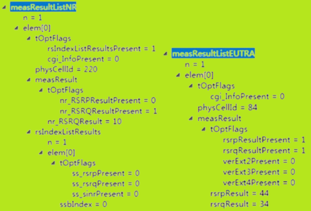
Handover Execution.
Below picture shows SN Release.

4G Handover Information About the Target Cell.
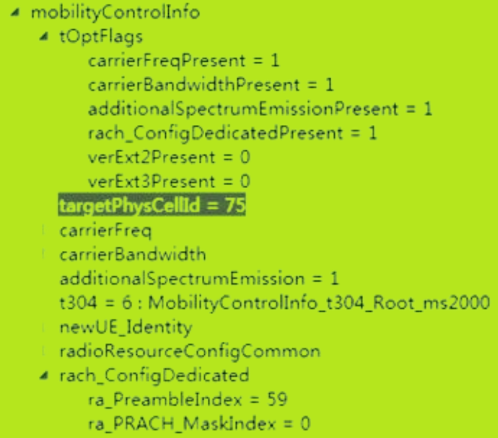
3. NSA Handover Delay.
In NSA (Non-Standalone) mode, handover delays can vary based on the frame structure used.

- Single-Period Frame Structure (2 ms):
- This version does not support handover with SN (Secondary Node) cells in the 5G NR (New Radio) network.
- This lack of support leads to a significant delay on both the 5G control plane and user plane.
- Dual-Frame Structure (2.5 ms, Q1 2019 Version):
- This version supports NSA handover with SN.
- The support provided by this structure greatly reduces the 5G delay during handover.
- Handover Delays in NSA Mode:
- The delays on the 4G control plane and user plane in NSA mode are essentially the same as those in a pure 4G network.
- The improvement in the 5G frame structure ensures that the additional delays typically associated with 5G are minimized.