Main keywords for this article are Instrumentation Test Procedure, Instrumentation Loops, Foundation Fieldbus Specifications, Signal Simulation, Instrumentation Loops Problems.
INSTRUMENTATION TEST PROCEDURE
The following test and inspection should be finished prior to this test.
1. Inspection for instrument calibration.
2. Test and inspection for instrument installation.
3. Test and inspection for cabling and wiring including termination.
4. Test and inspection for air supply piping.
5. Test and inspection for pneumatic signal tubing.
6. Test and inspection for the field junction box
7. Test and inspections for instruments hook- up tubing, if any.
Electric power and instrument air should be supplied properly prior to this test.
Actual Test and Inspection
Instrument loop shall be checked to determine that each item within the loop has the correct action and functions normally over the entire range. Actual Loop and/or Function test procedures shall be as follows;
Normal Check Instrumentation Loops
1. Loop shall be powered by its normal operating power source.
2. A process signal shall be produced at the transmitter by simulating output signal of the transmitter.
3. The simulated output signal shall be observed at all indicating and recording points in the loop.
4. If applicable, the signal shall be varied to check the operation of alarms. shutdown or other devices in the loop.
5. The controller output shall be checked at the controller and the control valve.
6. Alarm shall be checked with loop.
7. A simulated signal shall be made on each alarm and shutdown switch. Limit switch signal shall be confirmed with actual travel of the valves as much as practical.
8. Communication test shall be done separately.
Simple Check Instrumentation Loops
1. This simple check is only to monitor the loop, and observe its behavior.
There will be no modified or any signal simulation within the loop. This is to confirm the correctness of connections and response of the instruments and the controller via graphical display on the DCS.
Temperature Loop
Disconnect one side wire from TC or RTD terminal and indication changing shall be confirmed at final devices such as DCS (include recorder, ANNUNCIATOR etc).
Note: To disconnect one side of the TC/RTD from the head, do not disconnect at the transmitter.
Transmitter Loop
Disconnect one side wire from transmitter terminal and indication changing shall be confirmed at final devices such as DCS (include recorder, ANNUNCIATOR etc).
Control Output
Simple movement is confirmed at field. (no need confirmation for 0-100% detail movement).
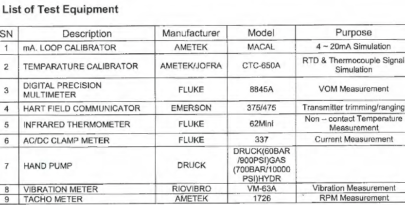
Test Equipment
The test equipment used in this test shall be in the effective period of calibration.
These equipment shall be stored and used under the direction of the charged personnel for the test work.
INDIVIDUAL TEST PROCEDURE
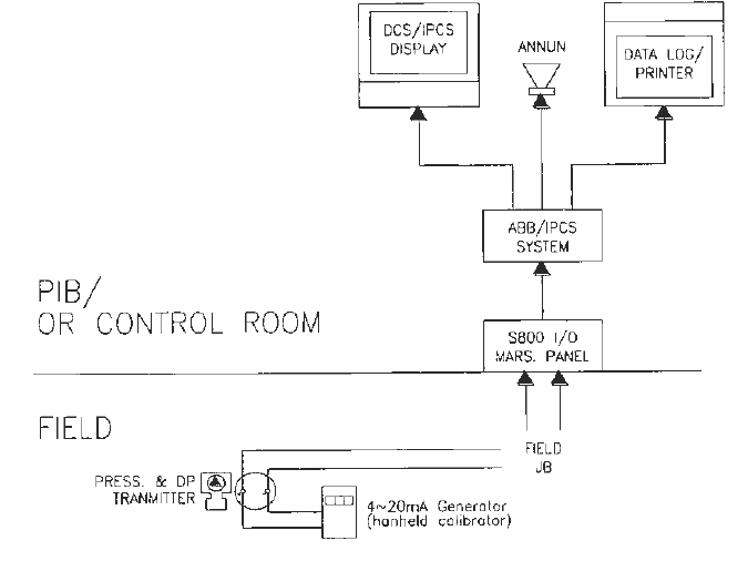
Analog Input Signal
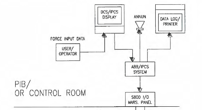
Analog input loop shall be checked at 0%, 25%, 50%, 75% & 100% of range by a 4 – 20mA from a mA signal generator.
A typical hook-up of loop test for analog input signal is shown in the attachments therein.
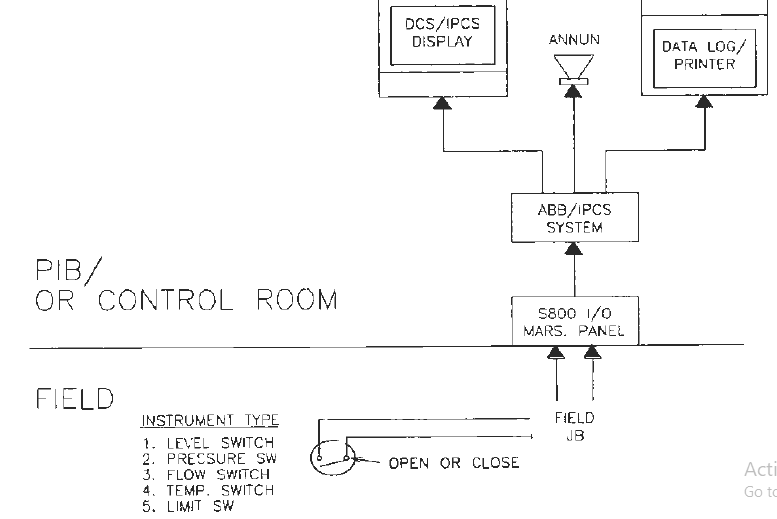
Digital Input Signal
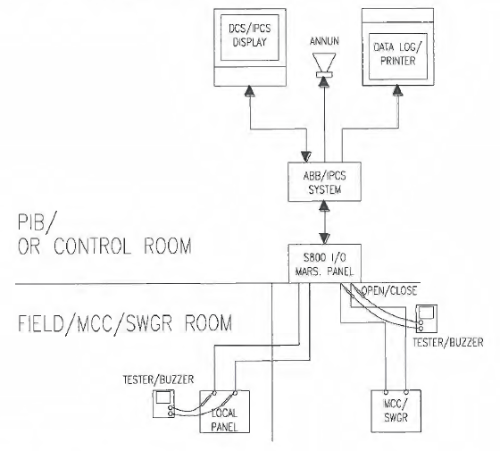
Digital input signal (except for limit switch) shall be checked by simulated signal of opening and/or closing of the cable at the terminal of field instruments. A typical hook-up of loop test for digital input signal is shown in the attachments therein.
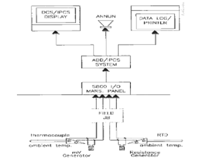
Temperature input loop shall be checked at 0%, 25%, 50%, 75% 100% of range by a mV in the case of thermocouples and resistance in the case of RTD’s by a mV and Resistance Generator respectively.
A typical hook-up of loop test for temperature input signal is shown in the attachments therein.
Analog Output Signal
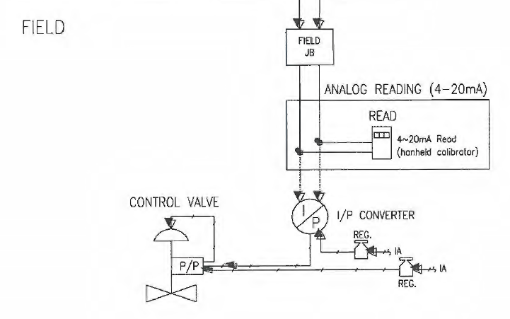
The controller output shall be checked at the controller and the control valve. The control valve position shall he checked at 0%, 25%, 50%, 75% & 100% of span by controller output signal.
With the valve at 0% go to -5% to ensure that the valve is on the seat.
With the valve at 100% go to 105% to ensure that the valve is wide open.
A typical hook-up of loop test for analog output signal is shown in the attachments therein.
Digital Output Signal (Run/Status, etc.)
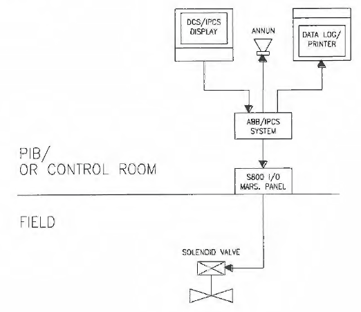
Solenoid valves shall be checked to actuate by force or mock test output signal from DCS/IPCS or by relay panel.
Dry contact relay (OV/+24VDC) shall be checked to actuate by force output signal from DCS/IPCS or by relay panel.
A typical hook-up of loop test for ON/OFF valve, run and status signal are shown in the attachments therein.
Foundation Fieldbus Instruments I/O Mock Test
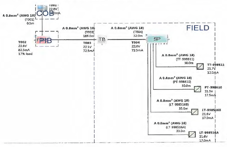
Instruments inter working with IPCS via segmentations or spurs and digitally process signal in a Foundation Fieldbus protocol and concept employed the use of transmitters and final control element installed at the site such as Pressure, Level, Flow, Temperature and other field devices connected with each other with host system.
Foundation Fieldbus Pre – Mock Test Procedure
The test procedure herein is intended for Fieldbus instruments as follows;
• Install all segments/spurs and interconnect power supplies and field equipment devices.
• Visually check cable shield continuity – ensure that the device shields are cut – back and insulated
• Ensure that cable are tested prior to physically connect to the device, check the cable color coding prior to termination
• Ensure to power up all networks and set the IPCS to scan all devices
• Run device tag list and check from the host system (IPCS)
Foundation Fieldbus Specifications
Data and specifications for validation below shall be checked with the host system and the documentation;
1. Number of Instruments connected
2. Number of segments or spurs
3. Instrument per segments
SIGNAL SIMULATION / INJECTION FLOW
Analog Input Signal
Digital Input Signal
Temperature Input Signal
Analog Output Signal (Control Valve)
Digital Output Signal (Run/Status, etc.)
ON/OFF Valve
Foundation Fieldbus Instruments
INSTRUMENTATION LOOPS PROBLEMS
Minor troubleshooting can be done such as checking the IPCS or DCS I/O’s fuse or checking the wire connection in the transmitter. If a significant amount of time is required then the loop team should continue with their planned work.
Document problems listing the tag number, I/O and type of problem. Give this to the person in-charge or his designee on a daily basis. A loop troubleshooting team to be organized during the actual loop test.
Note: We have discussed Main keywords for this article are Instrumentation Test Procedure, Instrumentation Loops, Foundation Fieldbus Specifications, Signal Simulation, Instrumentation Loops Problems.
