Following contents to be discussed for Electrical Switchgear. By reading this you will get complete idea about Electrical Switchgear.
- Introduction to SWGR.
- Switchgear Definition.
- Switchgear Function.
- Switchgear Applications.
- Switchgear Terminology.
- Low Voltage Switchgear types.
- Fault Level Calculations.
- FAT & SAT.

Complete Introduction to Switchgear
The objective of this article are
1. Know about SWGR Definitions & functions.
2. Understand SWGR specifications.
3. Increase Knowledge about Switchgear Terminology
4. Establishing a solid understanding of switchgear components.
5. To provide technical information on LV/MV switchgear used in common industrial, commercial and utility applications.
6. Know about FAT & SAT.
Switchgear Definition
Any switching and interrupting devices combined with associated control, regulating, metering, and protective devices, used primarily in connection with the Generation, Transmission, Distribution, and conversion of electric power.
Switchgear is Generic name to cover:-
▪ Air Circuit-breakers (ACBs).
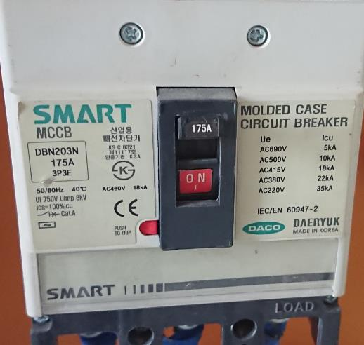
▪ Moulded –Case Circuit –breakers (MCCBs).
▪ Switches.
▪ Fuses.
▪ Switch-Disconnect-Fuses(SDFs).
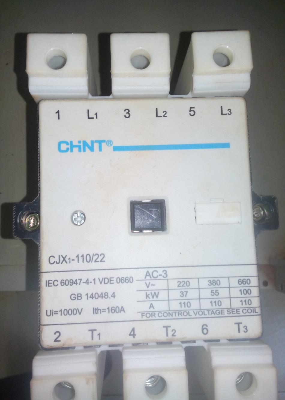
▪ Contactors.
▪ Relays.
▪ Motor-starters.
▪ Control Device.
▪ Switchboards

Switchgear Functional
| Switchgear | Switching | Protection |
| Contactor | Y | N |
| Relay | N | Y |
| starter | Y | N |
| Switch/SD | Y | N |
| HRC FUSE | N | Y |
| ACB | Y | Y |
| MCCB | Y | Y |
| MPCB | Y | Y |
| RCCB | Y | Y |
Switchgear Voltage Ranges (IEC 60038 Table I-IV)
| Voltage System | Nominal voltage (Vr) KV |
| LV | Vr < 1 |
| MV | 1 < Vr < 35 |
| HV | 35 < Vr < 230 |
| EHV(Extra high voltage) | 230 < Vr < 800 |
| UHV(Ultra High Voltage) | 800 < Vr |
Switchgear Applications:-
- Utilities

- Distribution Systems

- Oil and gas

- Industrial facilities

- Commercial building


Features required in switchgear :-
The following factors are important for switchgear and required by users:
- Safety.
- Overall cost.
- Availability.
- Ease of maintenance.
- Operator interface friendliness.
- Flexibility.
Switchgear Terminology
Switchgear Terminology are generally with respect to the following parameters:-
❖ Voltage.
❖ Currents.
❖ Behavior under normal & overload conditions.
❖ Behavior under short circuit conditions.
❖ Utilization categories.
Voltages
Rated Operational Voltage (Ue).
Rated Insulation Voltage (Ui).
Rated Impulse Voltage(Uimp)
Rated Operational Voltage (Ue).
This is the voltage that would normally be available continuously across the terminals of the different phases of switchgear .
This rating will be 415 V for LV switchgear. This implies that even while 415V @50Hz is present between the terminal there will not be any flash-over. That means the insulation between phases is sufficient
to tolerate a potential difference of 415 V continuously.
.")
Rated Insulation Voltage (Ui).
Considering that the worst condition of transformer tap changer in the max position (12.5%) and at the same time the system voltage fluctuation at the max (10%),so the net system voltage could be varying of up to +25% on the Switchgear. if the Switchgear is exactly rated for 415 V. then under the above conditions it would fail. so for this propose another rating called (Ui) is specified and normally this would be 690 V for low voltage Switchgear.
Even under the worst condition as described above ,the 415 V system voltage would not go beyond 690 V, so a Switchgear rated for Ui of 690 V would very well withstand the above condition.
.")
Rated Impulse Voltage (Uimp)
The impulse voltages are very high in magnitude ,with very short duration of voltage waves, typically have very high frequency. The impulse voltage either lightening Impulse (LI) or switching Impulse (SI). They can strike our system and our Switchgear might fail. so also this rating given for switchgear.
")
Currents
▪ Conventional Free Air Thermal Current (Ith).
▪ Conventional enclosed Thermal Current (Ithe).
▪ Rated operational Current(Ie).
▪ Rated uninterrupted Current(Iu).
▪ Rated Current(In) (Ir for HV CBs).
Switchgear Normal Condition Behavior
▪ Rated making capacity.
▪ Rated breaking Capacity.
Rated making capacity:-
This specification implies the maximum current – multiple of (Ie) – that the Switchgear can safely make, without fail or causing any damage to itself or to the installation or to the operator.
Rated breaking Capacity:-
This specification implies the maximum current – multiple of (Ie) – that the Switchgear can safely Break, without fail or causing any damage to itself or to the installation or to the operator.
Switchgear Short Circuit Condition Behavior
▪ Rated short circuit making current (Icm) (Ip).
▪ Rated short time withstand current (Icw) (Ik for HV CBs).
▪ Rated short circuit breaking current (Icn) [domestic-type CBs].
▪ Rated Ultimate S/C Breaking capacity( Icu) [for industrial CBs]
▪ Rated Service S/C Breaking capacity (Ics ).
Rated short circuit making current (Icm) (Ip) :-
This specification implies the maximum current that switchgear can safely make under the short circuit conditions without fail or causing any damage to itself or to the installation or to the operator.
Rated short circuit breaking current (Icn).
This is the maximum current that the switchgear can safely break under short circuit conditions, without fail or causing any damage to itself or to the installation or to the operator.
Rated short time withstand current (I cw).
This is the ability of the switchgear to carry the short circuit for the coordinated short circuit time ,it is called (I cw). This normally specified as 50 KA for 1 sec.
.")
Rated Ultimate S/C Breaking capacity Icu.
Circuit Breaker can break two faults of claimed Value and can make one fault of the claimed value. In other words: the circuit breaker must be able to break this current two times without causing damage, the breaker must be replaced or tested subsequently after two short circuits.

Rated Service S/C Breaking capacity Ics.
Circuit Breaker can break three faults of claimed Value and can make two fault of the claimed value. In other words: the circuit breaker must be able to break this current three times without causing damage, the breaker must subsequently be able to conduct its rated current without prior maintenance.

Rated Nominal current (In)
This is the maximum value of current that a circuit-breaker can carry indefinitely at an ambient temperature stated by the manufacturer, without exceeding the specified temperature limits of the current carrying parts.
Switchgear CB Utilization Category
According to IEC 60947-2, UC of a CB shall be stated with reference to whether or not it is specifically intended for selectivity by means of an intentional time delay with respect to other circuit breakers in series on the load side under short-circuits conditions.
Utilization category A(CAT A)
Circuit-breakers not specifically intended for selectivity under short-circuit conditions without A short time withstand current (MCCB).
Utilization Category B(CAT B)
Circuit-breakers specifically intended for selectivity under short-circuit conditions without A short time withstand current (ACB).

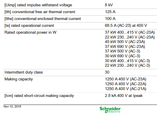
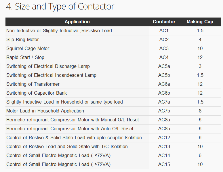
Contactor Utilization Category
CB Utilization Category

Switchgear Assembly
▪ Contactors, relays, Circuit Breakers (MCB, MCCB, MPCB, ACB) (Air Circuit Breaker).
▪ Fuses
▪ Switches ,Dis-connecter ,Isolator.
▪ Transformers.
▪ Instrumentation and control equipment,
▪ Three-phase bus work.
Low Voltage Switchgear types
1) Main Distribution board (MDB) panel
2) Sub Distribution board (SDB)panel
3) ATS/MTS( Automatic/Manual transfer switch)
4) MCC (Motor Control Center ) (DOL, star delta Starter ,soft starter)
1) Main Distribution board (MDB) panel


")

2) Sub Distribution board (SDB)panel
Use to Distribute power to the utilities of an installation such as :-
• Lighting loads
• Cooling and heating loads
• Water supplies (pump sets)
• Firefighting (pump sets)
• Lifts and escalators
• Welding sockets …..etc. for future maintenance of the installation.
 Sub Distribution board (SDB)panel")
3) ATS/ MTS( Auto/Man transfer switch)
Use to provide temporary electrical power if the utility source fails.
 ATS/ MTS( Auto/Man transfer switch)")
4) Motor control centers (MCC)
Use to Use for motor starting, which are:
1. Direct On Line
2. Primary Resistance
3. Auto-Transformer
4. Star Delta
5. Electronic Soft Start/VFD
 Motor control centers (MCC)")
 Motor control centers (MCC)")
FAULT LEVEL CALCULATIONS OF SWITCHGEAR
Fault level at any given point of the electric power supply network is the maximum current that would flow in case of a short circuit fault at that point.
Purpose Of Fault Level Calculations
- For Selecting Short Circuit Protective Devices Of Adequate Short Circuit Breaking Capacity.
- For Selecting Circuit Breakers & Switches Of Adequate Short Circuit Making Capacity.
- For Selecting Busbars, Busbar Supports, Cable & Switchgear, Designed To Withstand Thermal & Mechanical Stresses Because Of Short Circuit.
- To Do Current Based Discrimination Between Circuit Breakers.
Fault currents
TYPES OF SHORT CIRCUITS
Asymmetric Faults
➢L – E (SINGLE LINE TO EARTH).
➢L – L (LINE TO LINE).
➢L – L – E (LINE TO LINE TO EARTH).
Symmetric Faults
➢L – L – L (THREE PHASE).
SOURCES OF SHORT CIRCUIT CURRENTS
Supply
▪ Transformer
▪ Synchronous Generators
Loads
▪ Induction motors
▪ synchronous motors.
▪ Shunt capacitors
Nature Of Short Circuit Current
The Short Circuit Current Will Consist Of Following Components :
SOURCE : UTILITY SYSTEM
▪ The Ac Component With Constant Amplitude.
▪ The Decaying Dc Component.
SOURCE : SYNCHRONOUS GENERATORS & MOTORS / INDUCTION MOTORS
▪ The Ac Component With Decaying Amplitude
▪ The Decaying Dc Component


Switchgear Design and modeling:-
- Why modeling ??
- To predict the SWGR components (Sizing ,types, configuration, Assembling mapping ..ect)
- Thermal simulation of switchgear.
- Ease Of SWGR schematic and drafting
- Use to feed CADCAM machinery
Switchgear Factory and Site Tests
- Necessity to prove the performance before putting into service .
- Evolution of standards for HV/MV electrical equipments.
- Globalization resulting in common methods to assess the performance of equipments from different manufacturers of different countries .
- To give confidence about performance and safety to the end user before acceptance.
- Finished product includes many components independently tested and need final tests once assembled.
- All parts not visible hence need for a common method to check capability under actual working conditions.
- Base line test results used as basis for future comparisons of performance.
1- Switchgear FAT Tests
▪ These tests are carried out at the Manufacturer’s Factory .
▪ FAT tests are combination of routine tests, special tests and type tests .
▪ Normally customers choose which tests to do from the above listed tests(routine ,special ,type).
▪ The FAT is Performed according to the customer requirements at the witness of the customer or his representative/s.
a) Type tests/Design tests.
b) Routine tests.
c) Special tests.
(1) Routine tests :
-
- The IEC definition of routine tests is a test to which each individual equipment is subjected for example transformers routine tests are no load, short circuit, ratio etc .
- Each equipment may subject to routine test at least one time .
- Practically we find that a routine test can done to a certain equipment at the factory after manufacturing and at the site during commissioning tests.
(2) Type tests/Design tests :
-
- Type Tests are performed on single specified Electrical Equipment of one type and are intended to check the design characteristics.
- Type test usually relates to the first unit manufactured by a firm to given specification.
- For transformers type tests are temperature rise test and impulse tests. .
(3) Special tests :
-
- The IEC definition of a special test is a test done for electrical equipments other than a type test or a routine test agreed by the manufacturer and the purchaser .
- Type test and special test are carried out on the specific requirement of customers .
- For LV SWGR tests are ability to withstand sudden short circuit, seismic test ….etc.
2- Switchgear SAT Tests
SAT Stands for Site acceptance test (SAT)- are carried out during commissioning/pre commissioning at site. It include following :-
a) Pre-commissioning tests.
b) Commissioning tests.
c) Maintenance tests(Troubleshooting tests).
d) Tests after replacement /repair.
a) Pre-commissioning tests:
▪ These tests are done to assess the condition of an equipment after installation and comparing tests results to the factory test reports.
▪ Following are some examples for Precommissioning tests : –
1. Visual Check and Inspection.
2. Some of routine tests.
3. Test on auxiliary equipment.
b) Commissioning tests :
Process by which an equipment, facility, or plant (which is installed, or is complete or near completion) is tested to verify if it functions according to its design objectives or specifications.
c) Maintenance tests (Troubleshooting Test):
These are tests that is performed to:
1) Identify equipment problems or diagnose equipment problems.
2) prove that the rest of the system has not been affected by the maintenance work.
d) Tests after replacement/repair :
These tests are performed to be sure that insulation of the whole system is not affected after changes have been made if the system is extended or because of some additional features added to it.
VARIATIONS TO BE CONSIDERED WHEN TESTING ELECTRICAL SWITCHGEAR EQUIPMENT:
▪ The following three items are important in testing and design of electrical equipments .
1. Altitude above sea level
2. Ambient temperature
3. Humidity
▪ Tests results are to be corrected for climatic conditions .
1. ALTITUDE
-
- Air is an insulating medium with separation based on operating voltages.
- Increase in location altitude decreases the dielectric properties of the air.
- Normal test results satisfy equipments used in altitudes up to 1000 meters above sea level.
- Beyond this level we have to use equipments rated for slightly higher voltage.
2.TEMPERATURE
-
- Ambient temperature generally limited to 40ºC.
- Temperature rise generally measured based on this ambient temperature.
- Losses and some performance details corrected to 75ºC to reflect the actual operating temperature.
- For example Megger test results affects directly by the temperature at the time of testing .
3. Humidity
-
- In gases and liquids, the presence of humidity can cause a change in insulating performances.
- In the case of liquids, it always leads to a drop in performance.
- Humidity affects directly the electrical insulation and causes huge failures.
- In hard insulators like porcelain bushings, the humidity can make a flashover at normal voltage values .
4. Tolerances
-
- Tolerances in test results values is very important and the global specifications show us when to accept tolerances.
- Generally the equipment shall withstand the test voltages specified without tolerance.
- Losses, impedance, values, etc are designed related and based on many factors – standards allow tolerances for these values.
Switchgear Factory and site Tests
(A) Electrical Tests
1. Megger test.
2. High potential test 2500 VDC for 1 minute.
3. Operating test of all protective relays.
4. Testing of thermal relays with time clock and current injection set to check if relays stay within their curves.
5. Check correct bus phasing from each source and Checking of all control wiring.
6. All the auxiliary NO& NC points.
(B) Mechanical Tests
1. Mechanical indicators (Postion indicators ).
2. Mechanical tests (open & close operation , Earth Switch, door locks, etc. ).
3. Operating mechanism.
4. Check accessibility of bus bar connection bolts and nuts with normal tools.
5. proper mounting of components;
(C) General inspections
1. Constructive aspect, Appearance test ( painting, nameplates, labels etc.).
i. Correct labeling of functional units.
ii. Completeness of the data on the nameplate.
2. IP degree protection and the certificates.
3. Inspect indicating devices for correct operation.
4. Creepage distances and clearances.