In many industries where processes require heating, such as with different heaters and boilers, there’s a critical need to manage the risks that come with operating burners. This is where a specialized system, known as the Burner Management System (BMS), comes into play. The BMS uses advanced controls and safety measures to prevent incorrect use of the equipment and to address issues caused by equipment malfunctions safely.
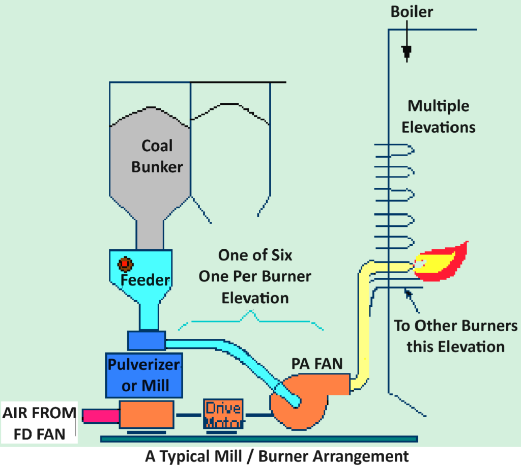
Without proper management, these issues could lead to dangerous situations like uncontrolled fires, explosions, structural failures, or accidental releases of hazardous materials. The system ensures that safety protocols are in place to handle these risks effectively, safeguarding both the operation and its surroundings. Below picture of typical mill burner management.

Burner Management System.
How Burner Management System (BMS) Works?
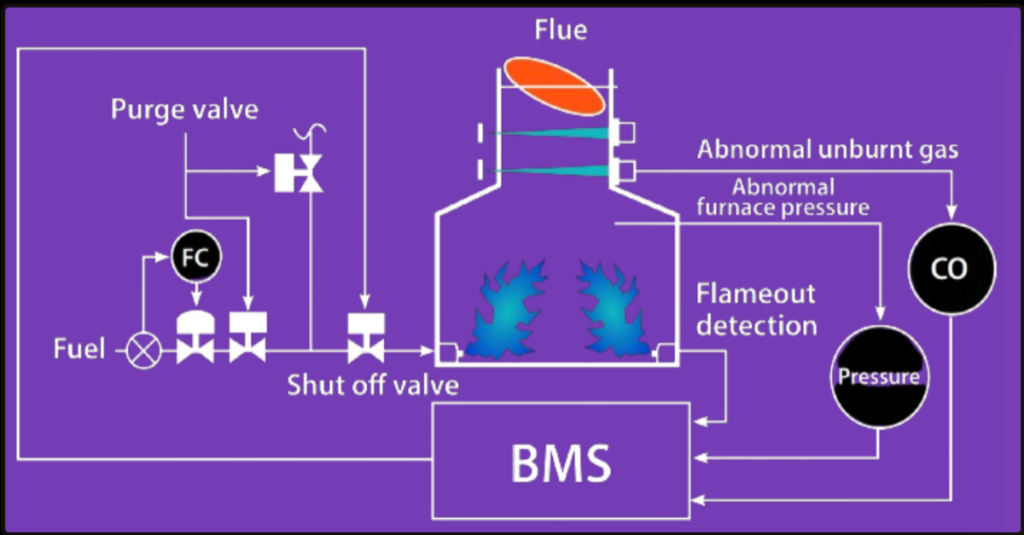
The Burner Management System (BMS) plays a pivotal role in monitoring and controlling the burners, igniters, flame detectors, and actuators like shutdown valves, ensuring safe operation of combustion systems. It encompasses a range of functions aimed at preventing unsafe conditions and facilitating a safe operating environment. These functions include:
- Inhibiting Startup: Prevents the initiation of the burner operation if pre-defined safe conditions are not met.
- Monitoring: Continuously observes the burner to identify any deviations from normal operation that might indicate unsafe conditions.
- Protection: Takes proactive measures to guard against conditions that could lead to safety hazards.
- Shutdown Interlocks: Implements safety interlocks that trigger an automatic shutdown in response to detected unsafe conditions, such as the absence of a flame or the presence of other hazardous situations.
When the system detects an absence of flame or unsafe operating conditions, it activates actuators to cut off the fuel supply, effectively inhibiting the flame and preventing potential accidents.

Methods of Implementing a BMS
Separated Method
The traditional approach to implementing a BMS involves a separate Safety Instrumented System (SIS) and a Basic Process Control System (BPCS):
- Safety Instrumented System (SIS): Focuses on the safety aspects, ensuring that emergency shutdowns and protective measures are triggered as required.
- Basic Process Control System (BPCS): Manages the routine control tasks for the process, such as temperature control, pressure management, and flow regulation.
In this configuration, the SIS and BPCS utilize separate logic solvers and are hosted on different equipment, with distinct workstations and SCADA software. However, they can communicate with each other using a bus system and a common communication protocol, ensuring coordinated operation despite their physical separation.
Integrated Method
The integrated method represents a modern approach to BMS implementation, where both the SIS and BPCS functionalities are combined within the same hardware and software systems:
- Unified System: The logic solving for both safety (SIS) and control (BPCS) functions is carried out by the same PLC (Programmable Logic Controller), which meets industry standards for safety integrity, such as SIL3 (Safety Integrity Level 3).
- Shared Workstations: Both safety and control operations are monitored and controlled from the same workstation, streamlining operations and reducing hardware requirements.
- Integrated SCADA: A single SCADA (Supervisory Control and Data Acquisition) system is used for both safety and control, enhancing data visibility and operational response times.
The choice between separated and integrated methods depends on factors such as the specific safety requirements, complexity of the process, regulatory considerations, and the preference for either centralized control and monitoring or a more segregated approach to safety and process control. The integrated method, with its consolidated control environment, offers advantages in terms of reduced equipment needs and potentially enhanced communication and response times, but it must be designed carefully to ensure that safety is not compromised.
Types of Burner Management System.
The evolution and types of Burner Management Systems (BMS) over the years reflects advancements in technology and the increasing need for safer, more efficient, and flexible combustion control systems. Here’s a look at how BMS technology has evolved and the key design features that enhance their safety and functionality:
Evolution of BMS Technologies:
1. 1950s – Relay-Driven Systems.
Early BMS were based on hard-wired, relay, and timer-driven systems. These systems were mechanical and relied on physical components to manage burner operations.
2. 1970s and 1980s – Solid State Systems.
These systems introduced solid-state processors and relays, marking a shift from purely mechanical components to electronic ones. This generation often used proprietary hardware, limiting flexibility and integration with other systems.
3. Microprocessor-Based Systems.
Systems like the Honeywell 7800 series represented a significant advancement with fixed logic controlled by microprocessors. These offered more reliability and control precision than their predecessors.
4. PLC-Based Systems.
The latest in BMS technology, PLC (Programmable Logic Controller) based systems are highly powerful, expandable, and versatile. They allow for complex logic, integration with other control systems, and adaptability to a wide range of applications.
4. Safety Instrumented Systems (SIS).
An SIS BMS includes safety functions designed to meet specific Safety Integrity Levels (SILs) as per international standards like IEC 61511. These systems focus on providing high levels of safety for high-risk applications.
Applications where the failure of the burner management could lead to significant safety, environmental, or economic risks, such as in large-scale power generation or chemical processing plants.
5. Smart / IoT-enabled Systems.
These BMS are equipped with smart, connected technologies that enable remote monitoring, diagnostics, and control capabilities. They can gather and analyze data for predictive maintenance and operational efficiency improvements.
Modern installations aiming for high efficiency, low emissions, and advanced operational insights. Suitable for industries moving towards Industry 4.0 standards.
6. Modular Systems.
Modular BMS solutions offer a flexible approach, allowing additional modules or components to be added as needed to expand functionality or to accommodate additional burners. Expanding facilities or applications where future scalability is a key consideration.
Key Design Features of Modern BMS:
- Critical Input Checking: Ensures that all essential input signals, such as temperature and pressure readings, are valid and within safe ranges.
- Critical Output Channel Monitoring: Monitors the outputs to ensure actuators and relays function as intended, preventing unsafe conditions.
- Electro-Mechanical Master Fuel Trip (MFT) Relay: Provides a failsafe mechanism to shut off the fuel supply in case of a critical system failure.
- Redundant Watchdog Timers: These timers monitor the system’s health and trigger a response if the system does not behave as expected within a set timeframe.
- Low Water Cut-Out Monitoring during Blowdown: Protects the boiler from damage due to low water levels during maintenance activities like blowdown.
Advanced Functionalities:
- Multiple Fuel Firing Capabilities: Allows the system to switch between different fuel types or mix them, enhancing flexibility and ensuring operation during fuel supply constraints.
- Redundant Scanners: Improve reliability by using multiple sensors to confirm flame presence and characteristics.
- Integration with SCADA: Allows for remote monitoring and control, historical data analysis, and trend analysis of burner operations, enhancing operational insights and safety management.
The continuous evolution of BMS technologies reflects the industry’s push towards greater safety, efficiency, and operational flexibility. Modern systems are designed to address the inherent risks in burner operations while providing the versatility needed to meet diverse industrial requirements.
Alarms.
In a Burner Management System (BMS), alarms are critical for signaling abnormal conditions or deviations from normal operating parameters, allowing operators to take corrective actions promptly. The alarms you’ve mentioned cover a variety of conditions that are crucial for the safe and efficient operation of combustion systems. Here’s a brief overview of each alarm and its significance:
- Burner Fuel Gas Header High Pressure: Indicates that the pressure in the fuel gas header is higher than normal, potentially leading to over-fueling of the burner and unsafe operating conditions.
- Furnace Pressure High Pressure Limit: Alerts when the pressure inside the furnace exceeds a safe limit, which could indicate a blockage or malfunction in the pressure relief system.
- Furnace Draft High Flow Limit: Signifies excessive airflow through the furnace, which could impact combustion efficiency or indicate a leak in the system.
- High Stack Temperature: Highlights an unusually high temperature in the exhaust stack, suggesting inefficient combustion or heat exchange, or potential damage to stack materials.
- Loss of Draft Fan: Indicates failure or shutdown of the fan responsible for maintaining appropriate airflow through the furnace, affecting combustion and potentially leading to unsafe conditions.
- Furnace Airflow Low Flow Limit: Warns of insufficient airflow in the furnace, which can lead to incomplete combustion and the accumulation of combustible gases.
- Loss of Interlock Power: Signals a disruption in the power supply to the safety interlocks, which could disable critical safety functions.
- Loss of Control Power: Alerts to a loss in the power supply to the control system, potentially leading to uncontrolled burner operation.
- Loss of Flame (Partial and Total): Indicates that the flame has been extinguished (totally or partially), which could lead to unburned fuel accumulating and creating an explosive hazard.
- Valve Mismatched Position: Warns that a valve is not in its expected position, which could affect fuel flow, air supply, or exhaust systems, leading to inefficient or unsafe conditions.
- Any Source of a Master Fuel Relay Trip (Cause of Trip Indication): Provides specific information about the cause of a safety trip, which shuts off the fuel supply to prevent unsafe conditions.
Each of these alarms is designed to alert operators to specific conditions that require immediate attention to prevent equipment damage, inefficiencies, or hazardous situations. Understanding the cause and appropriate response to each alarm is critical for maintaining the safety and operational integrity of combustion systems.
Objectives of BMS.
The Burner Management System (BMS) has key objectives to ensure the safety and efficiency of burner operations. These goals include:
- Safely Starting and Monitoring: It handles the safe initiation of the burner, including checking for any issues like the absence of a flame when there shouldn’t be one.
- Guaranteeing a Thorough Pre-purge: The system ensures that any potentially combustible gases or residues are cleared out before ignition, preventing dangerous conditions.
- Overseeing Safety Limits: While the burner is operating, the BMS keeps an eye on critical safety thresholds to prevent unsafe conditions.
- Monitoring Flame Presence: It continuously checks for the flame during operation to ensure the burner is functioning correctly.
- Managing Safe Shutdown: The system can safely turn off the burner, either when it’s supposed to at the end of its operation cycle or if there’s a problem.
- Integrating with Combustion Controls: It works together with the system controlling the mix of fuel and air to maintain efficient and safe combustion.
For a BMS to be effective, it should be designed following specific industry standards and guidelines. These include:
- NFPA 85/86 or other National Fire Protection Association standards: These provide broad safety guidelines for boiler and combustion systems to prevent fires and explosions.
- Industrial Risk Insurers (IRI) recommendations: These guidelines help manage risks associated with industrial operations.
- ISA 84: This standard from the International Society of Automation focuses on the safety of automated systems in industrial processes.
- Factory Mutual loss prevention guidelines: These are designed to minimize the risk of fire and equipment damage in industrial settings.
- Gastec for Europe: European standards for gas safety, focusing on the safe use and operation of gas systems.
These guidelines ensure that BMS designs consider a comprehensive set of safety, operational, and risk management principles, tailored to meet both regional and international requirements.
Scope of Work for BMS.
- Fuel Skid Process & Mechanical Design.
- BMS Logic, Electrical & Mechanical Design.
- Control Cabinets & Fuel Skids Fabrication.
- BMS & HMI Programming/Network Development.
- Full Burn-In, De-Bug & Factory Acceptance Test.
- BMS Installation Supervision.
- Complete “As-Built” Documentation Package.
- On-Site Commissioning & Training Services.
BMS Components.
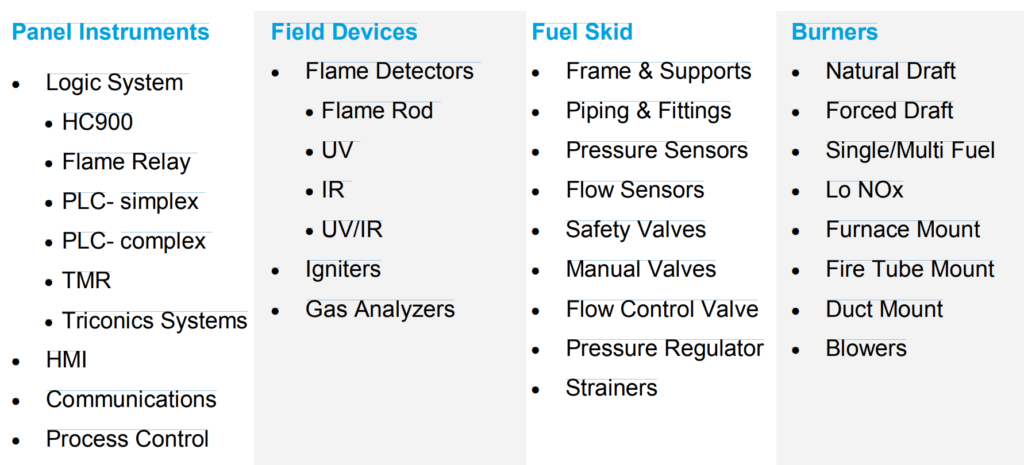
To get details and component functions, you can read BMS Components.

This table organizes the components into their respective categories for easier reference.