In this comprehensive article, we will delve into the minimum insulation resistance values and calculation formulas various categories of electrical equipment like Rotating Machinery, Cables and Conductors and Transformers etc.. From rotating machinery to cables, conductors, transformers, and more, we will explore the factors influencing these values and the significance of adherence to these standards. Whether you’re a seasoned electrical engineer or a novice in the field, this article will provide valuable insights into maintaining the electrical health of different equipment types through insulation resistance testing.
Minimum Insulation Resistance Values for Different Electrical Equipment
Minimum Insulation Resistance Values Rotating Machinery:
The IEEE guide, “Recommended Practices for Testing Insulation Resistance of Rotating Machinery,” offers guidance on conducting and interpreting insulation resistance measurements for rotating machinery. It addresses factors affecting insulation resistance, suggests standardized testing methods, and provides formulas for calculating approximate minimum insulation resistance values for various types of AC and DC rotating machinery. According to the guide:
Recommended minimum insulation resistance (Rm) for armature windings and field windings of both AC and DC rotating machines can be determined using the formula:
Rm = kV + 1
Where:
- Rm = Recommended minimum insulation resistance in megohms at 40°C for the entire machine winding.
- kV = Rated machine terminal-to-terminal potential in kilovolts.
For vital machinery, it is considered good practice to initiate reconditioning if insulation resistance, which had previously been well above the minimum value defined by the formula, drops significantly to approach that level.
It is recommended that operators and maintainers of rotating machinery obtain copies of the IEEE publication “Recommended Practices for Testing Insulation Resistance of Rotating Machinery”.
Bushings:
For outdoor oil circuit breaker bushings, experience has shown that each bushing, including its associated insulating components, should have an insulation resistance value exceeding 10,000 megohms at 20°C for reliable operation. This assumes the oil inside the tank is in good condition, the breaker is disconnected from external connections to other equipment, and the porcelain weather shield is safeguarded.
This requirement applies to individual components like the stripped bushing, cross-member, lift rod, lower arcing shield, and more. Any component that appears superficially clean and dry but has an insulation resistance below 10,000 megohms is typically internally deteriorated due to moisture or carbonized paths. Such components are not reliable for service unless reconditioned, especially under surge conditions like lightning disturbances.
For stripped oil circuit breaker bushings, both the lower stem and upper weather shield must be either perfectly clean or guarded before considering them unreliable due to an insulation resistance value lower than 10,000 megohms.
These guidelines apply to bushings used in other equipment, such as transformers. Given their typically high insulation resistance values, it is essential to use a Megger insulation tester with a range of at least 10,000 megohms for testing such equipment. Megger instruments with ranges up to 50,000 megohms are particularly useful for detecting deteriorating trends in bushings before they reach the questionable 10,000-megohm threshold.
Insulation Resistance of Cables and Conductors:
Cable and conductor installations exhibit a wide range of conditions affecting insulation resistance. These variations arise from factors like the type of insulating materials used, voltage ratings or insulation thickness, and the length of the circuit being measured. Additionally, these circuits often span long distances and may experience significant temperature fluctuations, which can impact the obtained insulation resistance values. The cleanliness and dryness of cable and conductor terminals are also critical, or they should be guarded against contamination.
The Insulated Cable Engineers Association (ICEA) provides minimum insulation resistance values in its specifications for various cable and conductor types. These minimum values are intended for new, single-conductor wires and cables that have undergone an AC high voltage test, with a DC test potential of 500 volts applied for one minute at a temperature of 60°F.
These standard minimum values (for single-conductor cable) are calculated using the following formula:
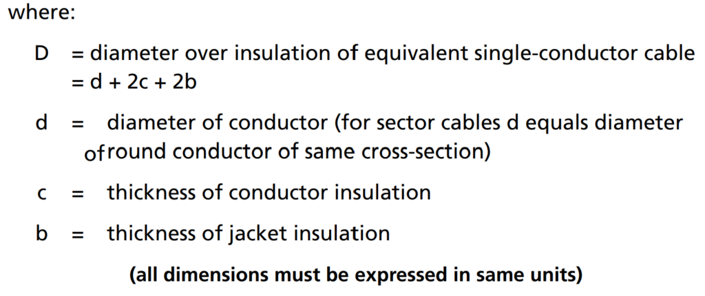
R = K log10 (D/d)
Where:
- R = Insulation resistance in megohms per 1000 feet of cable.
- K = Constant specific to the insulating material.
- D = Outside diameter of the conductor insulation.
- d = Diameter of the conductor.
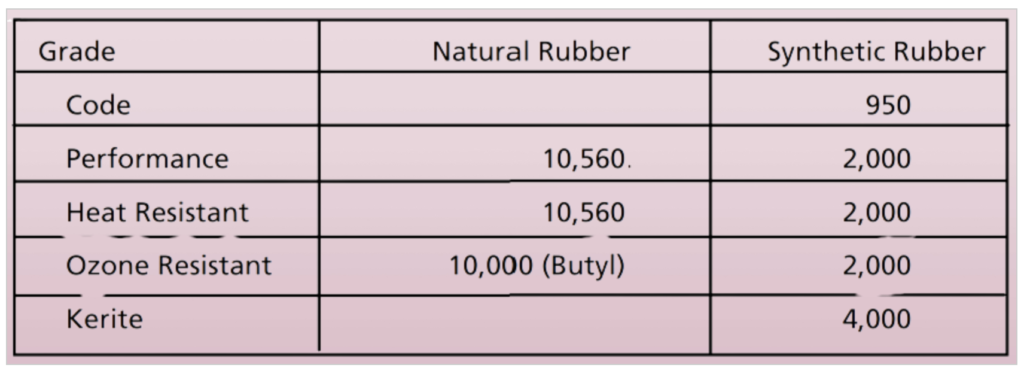
Minimum Values of K at 60°F for Various Insulation Types:
- Impregnated Paper: 2,640
- Varnished Cambric: 2,460
- Thermoplastic-Polyethylene: Above 50,000
- Composite Polyethylene: 30,000
- Thermoplastic-Polyvinyl:
- Polyvinyl Chloride 60°C: 500
- Polyvinyl Chloride 75°C: 2,000

The insulation resistance of one conductor of a multiconductor cable to all others and the sheath can be determined using appropriate testing procedures.
R = K log10 (D/d)

Minimum Insulation Resistance Values of Transformers:
Acceptable insulation resistance values for dry and compound-filled transformers should align with those recommended for Class A rotating machinery. However, there are no standard minimum values available for transformers.
Oil-filled transformers or voltage regulators introduce a unique challenge because the condition of the oil significantly influences the insulation resistance of the windings.
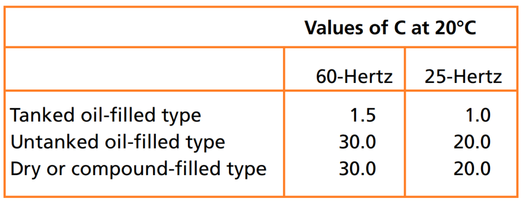
In the absence of more specific data, the following formula is suggested for determining minimum 1-minute 500-volt DC insulation resistance in megohms:
R = CE / √(kVA)
Where:
- R = Minimum insulation resistance in megohms.
- C = A constant for measurements at 20°C.
- E = Voltage rating of the winding under test.
- kVA = Rated capacity of the winding under test.
This formula assumes the transformer is filled with dry, acid-free, sludge-free oil, and that the bushings and terminal boards are in good condition.
It’s important to note that for tests where one winding is grounded while the other winding or windings are grounded, the insulation resistance values will be much lower than those calculated by the formula.

For single-phase transformers, use the formula as given. If you are testing a three-phase transformer where all three individual windings are being tested together, use the voltage rating of one of the single-phase windings and the rated capacity of the completed three-phase winding under test.
Related Articles:
What is Good insulation?
What Makes Insulation Go Bad?
How Insulation Resistance is Measured.
How to Interpret Resistance Readings.
Factors Affecting Insulation Resistance Readings.
Types of Insulation Resistance Tests.
Test Voltage vs. Equipment Rating.
AC Testing vs. DC.
Use of DC Dielectric Test Set.
Tests During Drying out of Equipment.
Effect of Temperature on insulation Resistance.
Effects of humidity.
Preparation of Apparatus to test.
Safety Precautions.
Connections for testing insulation resistance of electrical equipment.
Additional Notes About using A Megger Insulation Tester.
Interpretation-Minimum Values.
Tests Using Multi-Voltage Megger Insulation Testers.
Step-Voltage Method.
Use of a Guard Terminal.
Outdoor Oil Circuit Breaker.