In 5G NR (New Radio), the handover principles in Standalone (SA) mode are similar to those in 4G LTE. This article focuses on the handover principles in Non-Standalone (NSA) mode. In NSA, the mobility management is divided into two categories: intra-LTE and intra-NR.
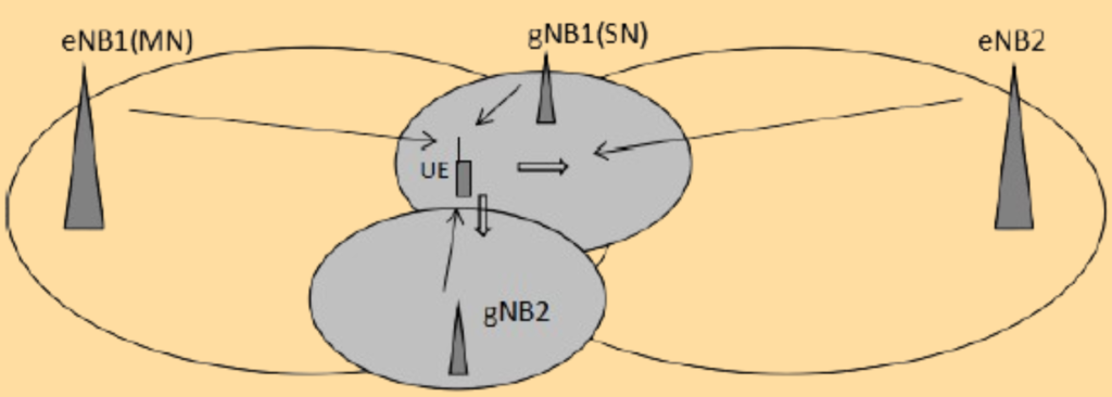
1. Intra-LTE Mobility.
In this scenario, the handovers include Secondary Node (SN) addition and SN release.
Here’s the process:
MN Handover:
- Scenario: The UE (User Equipment) has established LTE/NR dual connectivity in the coverage area of eNB1 and gNB. When the UE moves to eNB2, an MN handover is triggered from eNB1 to eNB2.
- Procedure: The source MN initiates the SN release procedure before the handover to release the SN. After the handover is successful, the SN addition procedure is triggered to add the SN to the target MN.
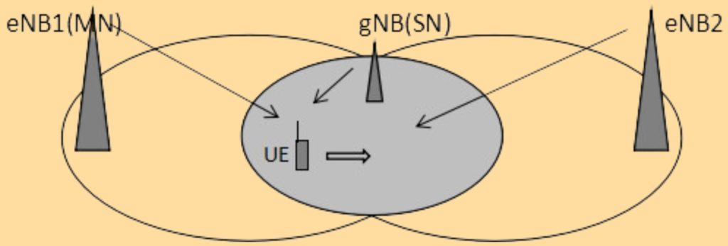
2. Intra-NR Mobility.
In 5G NR, handovers ensure that a User Equipment (UE) maintains a stable connection while moving. When the UE is moving within the NR service area.
- A3 Measurement Report: Triggered when the NR network has intra-frequency (same frequency) neighbor cells configured. This report can initiate a PSCell (Primary Secondary Cell) or SN (Secondary Node) change.
- A2 Measurement Report: Triggered when there are no intra-frequency neighbor cells. This report is used to release the SN.
Moving Within the NR Service Area.
When the UE moves within the NR service area and detects a neighboring cell with better signal quality, a handover occurs. The type of handover depends on whether the new cell is within the same gNB (local gNB) or a different gNB.
- Receive A3 Measurement Report:
- The UE sends an A3 measurement report to the SN.
- The SN selects the gNB with the best signal quality from the list of candidate PSCells and ranks them based on signal quality.
- Check If the gNB Is Local:
- If the selected gNB is the same as the current one (local gNB), proceed to Step 3.
- If the selected gNB is different, skip to Step 4.
- Execute PSCell Change:
- The gNB checks if any NR cell in the candidate list is configured for a PSCell change.
- If so, the gNB and UE perform the PSCell change procedure.
- Execute SN Change:
- If the gNB is not local or no suitable PSCell is found, the gNB and UE perform the SN change procedure.
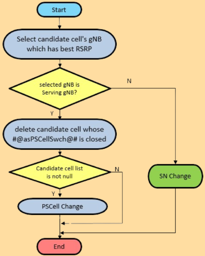
Intra-NR mobility involves the handover within NR service areas. There are two primary procedures: PSCell change and SN change.
1. PSCell Change:
When a User Equipment (UE) is connected to both LTE (eNB1) and 5G NR (gNB) cells and moves to a new area with better signal quality, a PSCell (Primary Secondary Cell) change may occur. Here’s a step-by-step explanation:
- Initial Setup:
- The UE is connected to eNB1 Cell1 and gNB Cell1 through dual connectivity.
- Moving Towards a New Cell:
- The UE moves towards the coverage area of Cell2.
- When the signal quality of Cell2 is better than Cell1 and the A3 measurement threshold is reached, the UE sends an A3 measurement report.
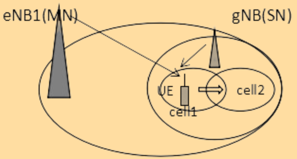
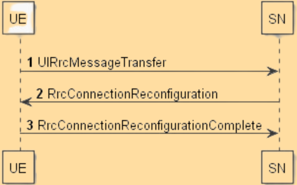
PSCell Change Procedure.
- Triggering the Report:
- The UE sends an A3 measurement report to the source SN (Secondary Node, which is the gNB) via the UL RRC (Uplink Radio Resource Control) MESSAGE TRANSFER message.
- Deciding on the Change:
- The SN analyzes the measurement report and decides to perform a PSCell change.
- The SN sets up the necessary resources for the target cell (Cell2).
- The SN sends an RRC CONNECTION RECONFIGURATION message to the UE to reconfigure the air interface.
- Reconfiguring the UE:
- Upon receiving the RRC CONNECTION RECONFIGURATION message, the UE deletes the configuration of the source cell (Cell1).
- The UE sets up the configuration for the target cell (Cell2).
- The UE sends back an RRC CONNECTION RECONFIGURATION COMPLETE message to the SN.
- Finalizing the Change:
- Upon receiving the RRC CONNECTION RECONFIGURATION COMPLETE message, the SN deletes the configuration of the source cell.
- The new configuration for the target cell takes effect, completing the PSCell change.
2. SN Change.
When a User Equipment (UE) moves to a new area with better signal quality, a change from one Secondary Node (SN) to another can occur. Here’s a step-by-step explanation:
Initial Setup:
The UE is connected to eNB1 and gNB1 through dual connectivity.
Moving Towards a New SN:
- The UE moves towards the area covered by gNB2.
- When the signal quality of gNB2 becomes better and the A3 measurement threshold (parameter @RptCfgPSCellChangeIntraF.A3offset@#) is reached, the UE sends an A3 measurement report.
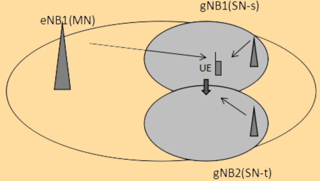
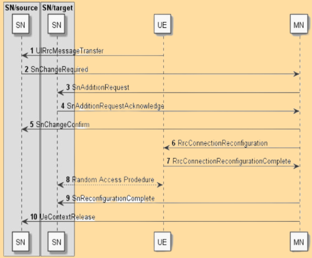
SN Change Procedure.
- The UE sends an A3 measurement report to the source SN.
- The source SN decides on the SN change and sends an SN CHANGE REQUIRED message to the Master Node (MN).
- The MN initiates the SN addition procedure by sending an SN ADDITION REQUEST to the target SN.
- Upon completion, the MN sends an RRC CONNECTION RECONFIGURATION message to the UE.
- The UE configures the target SN and performs non-contention-based random access to synchronize with the target SN.
- The MN confirms the SN reconfiguration and releases the source SN’s resources.
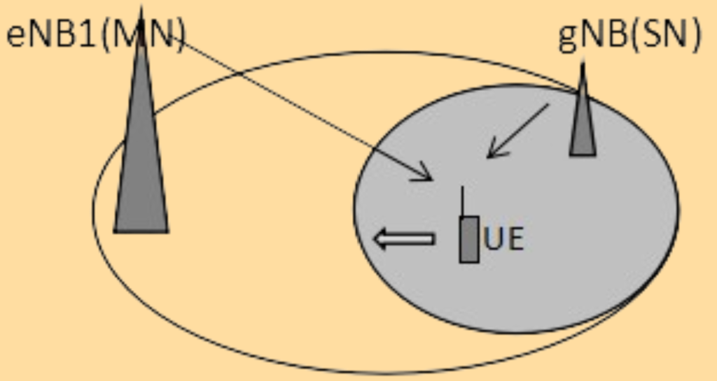
2. UE Moving to the Edge of the NR Service Area.
When the UE moves towards the edge of the NR service area, and the signal quality deteriorates, the A2 measurement threshold (#@RptCfgDcRelPSCellA2.A2ThresholdRsrp@#) is reached. The UE reports an A2 measurement and triggers the SN release procedure.
3. NR Handover Measurement Mechanism.
In 5G NR (New Radio), the handover process consists of three main steps: measurement, decision, and execution. These steps ensure that the UE (User Equipment) maintains the best possible connection as it moves.
- Measurement:
- The UE receives information for measuring the NR SSB (Synchronization Signal Block) and EUTRAN CSI-RS (Channel State Information Reference Signal) through the
RRCConnectionReconfigurationmessage.
- The UE receives information for measuring the NR SSB (Synchronization Signal Block) and EUTRAN CSI-RS (Channel State Information Reference Signal) through the
- Decision:
- The gNodeB (gNB) evaluates the Measurement Report (MR) sent by the UE. The MR can be periodic or triggered by specific events.
- The gNB determines if the relevant threshold is reached to decide whether a handover is needed.
- Execution:
- The gNB sends the target cell information for the handover to the UE.
A3 Event-Based Handover
An A3 event is one of the conditions used for triggering handovers. The handover process based on the A3 event is as follows:
- Condition for Reporting:
- When the UE meets the condition Mn+Ofn+Ocn+Hys>Ms+Ofs+Ocs+OffMn + Ofn + Ocn – Hys > Ms + Ofs + Ocs + Off for a period called Time to Trigger, a measurement report will be sent. This indicates the neighbor cell’s signal is sufficiently better than the serving cell’s signal.
- Condition for Stopping:
- When the UE meets the condition Mn+Ofn+Ocn+Hys < Ms+Ofs+Ocs+Off the A3 measurement stops. This indicates the neighbor cell’s signal is not better than the serving cell’s signal.
Parameters Explained
- Mn: Measured value of the neighbor cell.
- Ofn: Frequency offset of the neighbor cell.
- Ocn: Offset of the neighbor cell.
- Hys: Hysteresis value, used to prevent frequent switching.
- Ms: Measured value of the serving cell.
- Ofs: Frequency offset of the serving cell.
- Ocs: Offset of the serving cell.
- Off: Additional offset.
4. NR Handover Policy.
In NR (New Radio), several handover events can be used to manage mobility and ensure optimal connectivity for the User Equipment (UE). Here are the handover events and their definitions:
Handover Events
- Event A1:
- The signal strength of the serving cell is higher than an absolute threshold. Ensures the UE stays connected to the serving cell when the signal is strong.
- Event A2:
- The signal strength of the serving cell is lower than an absolute threshold. Indicates the need to leave the serving cell due to weak signal.
- Event A3:
- The signal strength of the neighbor cell minus the signal strength of the serving cell is higher than a relative threshold. Triggers when a neighboring cell has a significantly better signal compared to the serving cell.
- Event A4:
- The signal strength of the neighbor cell is higher than an absolute threshold. Indicates a neighboring cell with a strong signal that could be a candidate for handover.
- Event A5:
- The signal strength of the neighbor cell is higher than an absolute threshold and the signal strength of the serving cell is lower than an absolute threshold. Used to trigger handover when the serving cell’s signal is weak and a neighboring cell’s signal is strong.
- Event A6:
- In carrier aggregation (CA), when the RSRP/RSRQ/SINR difference between the secondary carrier and the local cell is larger than the dB value of the A6 threshold. Triggers a measurement report including the RSRP/RSRQ/SINR value for secondary carriers.
- Event B1:
- The signal strength of the inter-RAT (Radio Access Technology) neighbor cell is higher than an absolute threshold. Used for handovers to a different RAT, such as from NR to LTE or vice versa.
- Event B2:
- The signal strength of the serving cell is lower than an absolute threshold and the signal strength of the inter-RAT neighbor cell is higher than an absolute threshold. Triggers when leaving a weak serving cell for a stronger inter-RAT neighbor cell.
Recommended Handover Policies
Here are the recommended handover policies based on different events and scenarios:
- Coverage-based intra-frequency measurement:
- Events: A3, A5
- Usage: For maintaining optimal coverage within the same frequency.
- Release of the SN cell:
- Event: A2
- Usage: Indicates when to release a Secondary Node (SN) due to weak signal.
- Change of an SN cell:
- Event: A3
- Usage: For switching to a better SN cell within the same frequency.
- Addition of Scell measurement for CA:
- Event: A4
- Usage: Adds secondary cells for carrier aggregation when the neighbor cell has a strong signal.
- Deletion of Scell Measurement for CA:
- Event: A2
- Usage: Removes secondary cells for carrier aggregation when the serving cell’s signal is weak.
- Coverage-based inter-frequency measurement:
- Events: A3, A5
- Usage: For maintaining optimal coverage across different frequencies.
- Enabling inter-frequency measurement for handover:
- Event: A2
- Usage: Starts measuring other frequencies when the serving cell’s signal is weak.
- Disabling inter-frequency measurement for handover:
- Event: A1
- Usage: Stops measuring other frequencies when the serving cell’s signal is strong.
These policies and events help in managing seamless handovers, ensuring that the UE remains connected to the best possible cell, thus providing optimal performance and user experience.
Summary
The handover principles in 5G NR, particularly in NSA mode, involve complex procedures to ensure seamless connectivity and optimal performance. These processes involve coordination between eNBs, gNBs, and the UE, with specific measurement reports and signaling messages facilitating efficient mobility management.