The Radio Resource Control (RRC) protocol in LTE is essential for managing the radio interface connection.
Radio Resource Control (RRC) Protocol.
What is RRC Protocol?
Here are the main functions and responsibilities of the RRC protocol:
1. Setup, Reconfiguration, and Release of Radio Interface Connection:
RRC Establishes the initial connection between the UE and the network. Adjusts the parameters of an existing connection to meet new requirements or improve performance. Terminates the connection when it is no longer needed.
2. SRBs, Default and Dedicated Radio Bearers:
RRC protocol is responsible for carrying RRC and NAS signaling messages. Used for carrying default, best-effort IP traffic. Allocated for specific services with QoS requirements.
3. QoS Control and Initial Security Activation:
RRC protocol manages QoS parameters to ensure the necessary quality for different types of traffic. Activates security measures like encryption and integrity protection for the connection.
4. Paging UEs:
RRC protocol is used to establish mobile-terminated connections by requesting the UE to initiate a connection setup.
5. Broadcasting System Information:
Provides network-specific access parameters that are broadcasted by all cells. Helps UEs in accessing the network by supplying necessary configuration details.
6. Measurement Reporting and Mobility Procedures:
UEs report various measurements to the eNB (e.g., signal strength, quality). These reports can trigger intra-LTE or inter-RAT (Radio Access Technology) handovers. RRC handles all mobility procedures to ensure seamless transitions between cells or different RATs.
7. Error Recovery and RRC Re-Establishment:
Supports the “always-on” scenario by quickly re-establishing a dropped RRC connection. This function is crucial for maintaining ongoing sessions and ensuring minimal service disruption.
Differences Between LTE RRC and 3G UTRAN RRC:
- Simplified Signaling Messages: LTE RRC has fewer signaling messages compared to 3G UTRAN RRC, making it look simpler at first glance.
- Complex Reconfiguration Procedures: Despite fewer messages, the RRC reconfiguration procedure in LTE is complex. It combines multiple functions covered by separate procedures in 3G UTRAN RRC, such as:
- Physical channel reconfiguration.
- Transport channel reconfiguration.
- Radio bearer setup, reconfiguration, and release.
- RRC measurement control.
Due to this complexity, identifying what exactly is reconfigured in LTE can be challenging.
Overall, the RRC protocol in LTE plays a critical role in ensuring efficient and reliable communication by managing the radio resources and maintaining connection quality through various control and recovery mechanisms.
1. RRC States.
In LTE, there are only two RRC (Radio Resource Control) states, unlike 3G UMTS which had four. These states determine whether the radio connection between a user device (UE) and the network is active or inactive.
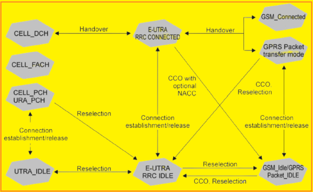
RRC_IDLE State:
In this state, the radio connection is inactive. The UE’s mobility is not controlled by the network, and it does not need to send measurement reports. However, the UE performs neighbor cell measurements for cell selection or reselection. It monitors the Paging Channel (PCH) for incoming calls and the Broadcast Control Channel (BCCH) for system information. The Master Information Block (MIB) is the most critical part of this information, with other system information sent on the Downlink Shared Channel (DL-SCH).
RRC_CONNECTED State:
In this state, the radio connection is active. The UE can send and receive data in both uplink (UL) and downlink (DL) directions. It measures the downlink radio quality of neighboring cells and sends RRC measurement reports as configured by the MME (Mobility Management Entity). The eNodeB and MME manage handover decisions and execution. The UE also monitors the PCH for incoming calls and reads system information on the DL-SCH, including changes in system parameters from System Information Block 1 (SIB1).
Inter-RAT Mobility:
When moving between different Radio Access Technologies (RATs), the UE transitions from LTE RRC states to 3G UMTS or GSM states.
- In IDLE mode, the UE reselects the best available RAT based on radio quality measurements and registers with the network.
- For UEs in CELL_PCH or URA_PCH states in 3G UTRAN, there is no active radio connection, but RRC context information is stored in the RNC. The UE can change to E-UTRA IDLE without further notice.
Handover Procedures:
- From E-UTRA RRC CONNECTED to 3G UMTS, the UE enters the CELL_DCH state.
- From E-UTRA RRC CONNECTED to GERAN, it ends up in GSM_CONNECTED for voice services after CS Fallback or GPRS Packet Transfer Mode for non-real-time services.
Cell Change Orders (CCO):
The UE can be ordered to change from E-UTRA RRC CONNECTED to GSM_IDLE/GPRS Packet_IDLE or from GPRS Packet Transfer Mode to E-UTRA RRC IDLE. After this, the UE must establish a radio connection and register with the network before data transfer can continue. To minimize registration delays, the Network Assisted Cell Change (NACC) was introduced, reducing the registration time to around 10 seconds.
2. System Information in LTE.
In LTE, system information is divided into the Master Information Block (MIB) and several System Information Blocks (SIBs).
Master Information Block (MIB):
The MIB includes key information such as the downlink transmission bandwidth and PHICH (Physical Hybrid-ARQ Indicator Channel) information of the broadcasting cell. It is transmitted on the Broadcast Channel (BCH) and mapped onto the Physical Broadcast Channel (PBCH). The MIB is the only system information sent on the BCH, while all other SIBs are transmitted using the Downlink Shared Channel (DL-SCH).
System Information Blocks (SIBs):
- SIB 1: Contains critical information like the PLMN (Public Land Mobile Network) identity, tracking area code, and cell identity (CI) of the broadcasting cell. It also includes the minimum Reference Signal Received Power (RSRP) threshold (Q-RxLevMin) for initial cell selection and random access, as well as scheduling information for other SIBs. SIB 1 is sent periodically every 80 milliseconds.
- SIB 2: Provides information on timers, constants, barring information, uplink (UL) frequency, and UL bandwidth.
- SIB 3: Contains parameters for cell reselection procedures.
- SIB 4: Provides neighbor cell information for intra-frequency cell reselection.
- SIB 5: Contains information for inter-frequency cell reselection.
- SIB 6: Provides details for inter-Radio Access Technology (RAT) cell reselection to UTRAN (3G).
- SIB 7: Contains information for inter-RAT cell reselection to GERAN (2G GSM).
- SIB 8: Provides information for inter-RAT cell reselection to CDMA2000.
- SIB 9: Used to broadcast the home eNB (eNodeB) name.
- SIB 10 and SIB 11: Used to broadcast warning information to subscribers, such as tsunami warnings.
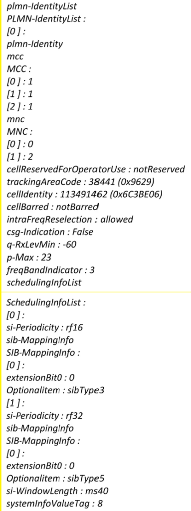
Transmission and Scheduling:
- The MIB is transmitted on the BCH and mapped to the PBCH.
- All other SIBs are transmitted on the DL-SCH, with SIB 1 being signaled on the Physical Downlink Control Channel (PDCCH) using a System Information Radio Network Temporary Identifier (SI-RNTI).
- MIB is transmitted every 40 milliseconds, while SIB 1 is transmitted every 80 milliseconds. Other SIBs are flexibly scheduled based on network configuration.
This structured transmission of system information ensures that user equipment (UE) can efficiently access essential data for network operations, cell selection, and reselection processes.
3. RRC Measurements in LTE.
In LTE, as in 3G UTRAN, RRC (Radio Resource Control) measurement reports are primarily sent based on event triggers. These events are designed to indicate significant changes in radio conditions, which are then used to make handover and cell reselection decisions. The key events and their descriptions are outlined in Table below:
Table: RRC Measurement Event IDs and Descriptions
- A1: Serving cell becomes better than a defined threshold.
- A2: Serving cell becomes worse than a defined threshold.
- A3: A neighboring cell becomes better than the serving cell by a defined offset.
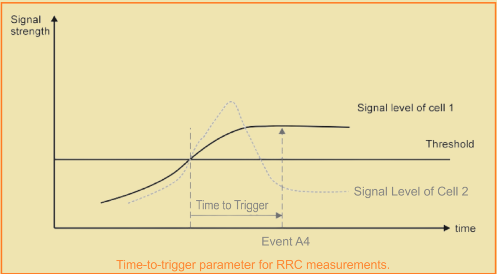
- A4: A neighboring cell becomes better than a defined threshold.
- A5: Serving cell becomes worse than a first threshold, and a neighboring cell becomes better than a second threshold.
- B1: An inter-RAT (Radio Access Technology) neighbor becomes better than a defined threshold.
- B2: Serving cell becomes worse than a first threshold, and an inter-RAT neighbor becomes better than a second threshold.
Thresholds and Parameters:
- Thresholds: Events are triggered based on signal strength measurements like RSRP (Reference Signal Received Power) or RSRQ (Reference Signal Received Quality).
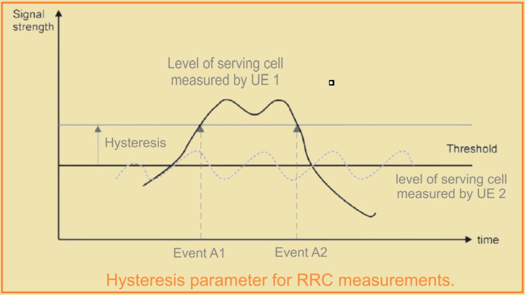
- Hysteresis: This parameter helps prevent frequent toggling (ping-pong effect) between cells by adding a margin to the threshold.
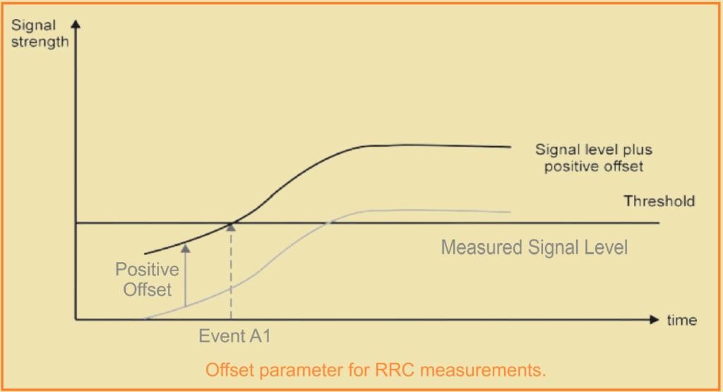
- Offset: This can be a positive or negative value used to adjust the measurement result to either speed up or slow down handovers. It is not tied to a predefined threshold.
- Time-to-Trigger: This parameter ensures that only persistent changes in radio conditions trigger a report, preventing brief signal fluctuations from causing unnecessary handovers.
For example, the hysteresis parameter prevents UE (User Equipment) from sending reports for short-term signal fluctuations, ensuring stability in measurement reporting. In Figure below, events A1 and A2 would be reported by UE 1 but not by UE 2 due to the hysteresis parameter.
The offset parameter, shown in Figure below, adjusts the timing of handovers. Positive or negative offsets can expedite or delay the handover process, respectively.
Time-to-Trigger, depicted in Figure below, helps avoid handovers triggered by short-lived peaks in signal quality. It ensures that handovers only occur when a cell offers stable and superior radio conditions over a specified duration.
Overall, these parameters and event triggers help maintain reliable and efficient network performance by ensuring that only significant and sustained changes in radio conditions prompt handover and cell reselection processes.