Carrier aggregation (CA) in 5G NR enhances bandwidth by combining multiple carriers, known as component carriers (CCs). This technology supports up to 16 contiguous and non-contiguous CCs with varying numerologies in both Frequency Range 1 (FR1) and Frequency Range 2 (FR2).
The number of downlink (DL) radio channels aggregated is equal to or greater than the number of uplink (UL) channels. Each radio channel can have a different numerology, which refers to the subcarrier spacing and symbol duration.
Several patterns exist for aggregating radio channels:
- Intra-band contiguous CA: Radio channels are contiguous within the same frequency band.
- Intra-band non-contiguous CA: Radio channels are spaced out within the same frequency band with maximum frequency separation.
- Inter-band CA: Radio channels are located in different frequency bands.
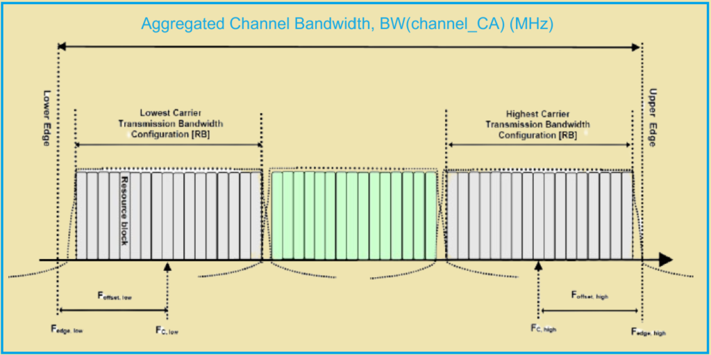
For contiguous intra-band aggregation, the total bandwidth and guard bands are calculated based on the configuration of the edge channels. In non-contiguous intra-band aggregation, the bandwidths are defined by sub-blocks, which can consist of multiple aggregated channels.

The aggregation notation determines the bandwidth class, including:
- The number of CCs per sub-block.
- The bandwidth per channel.
- The total aggregated channel bandwidth.
- A fallback group number.
A terminal configured with a specific bandwidth class can move to a lower class within the same fallback group or release a DC radio channel if necessary.
Different configurations for carrier aggregation include:
- Contiguous intra-band: Denoted by CA_nX, Class (e.g., CA_n77C), where nX is the band number and Class indicates the aggregation category.
- Non-contiguous intra-band: Denoted by CA_nX (Class1, Class2) (e.g., CA_n77 (3A–C)).
- Inter-band: Denoted by CA_nXA, nYA (e.g., CA_n77-n79).
Band numbers for FR1 and FR2 are defined in 3GPP TS 38.101-1 and 3GPP TS 38.101-2, respectively. Each band number is associated with a maximum bandwidth and the appropriate numerologies. For FR1, the inter-band configuration can include up to four bands. However, inter-band configurations for FR2 are not standardized in 3GPP Release 16.
Read Also: What is 5G NR Frequency Bands?
5G Carrier Aggregation in the FR1 Band.
1. Carrier Aggregation Class.
In 5G NR 3gpp Release 16 for the FR1 band, the radio bandwidth classes are categorized to define the maximum transmission band configuration for each component carrier (CC) aggregate radio channel. The classes are structured as follows:

- Class A: This corresponds to a 5G-NR configuration without carrier aggregation. The maximum 5G carrier bandwidth (BWChannel, max) depends on the band number and the numerology, which defines the sub-carrier spacing (SCS). Class A belongs to all fallback groups and allows the mobile to return to a basic configuration without carrier aggregation.
- Class B: This class supports a total bandwidth between 20 MHz and 100 MHz by aggregating two radio channels.
- Class C: This class supports a total bandwidth between 100 MHz and 200 MHz by aggregating two radio channels.
- Class D: This class supports a total bandwidth between 200 MHz and 300 MHz by aggregating three radio channels.
- Class E: This class supports a total bandwidth between 300 MHz and 400 MHz by aggregating four radio channels.
Classes C, D, and E belong to Fallback Group 1.
- Class G: This class supports a total bandwidth between 100 MHz and 150 MHz by aggregating three radio channels.
- Class H: This class supports a total bandwidth between 150 MHz and 200 MHz by aggregating four radio channels.
- Class I: This class supports a total bandwidth between 200 MHz and 250 MHz by aggregating five radio channels.
- Class J: This class supports a total bandwidth between 250 MHz and 300 MHz by aggregating six radio channels.
- Class K: This class supports a total bandwidth between 300 MHz and 350 MHz by aggregating seven radio channels.
- Class L: This class supports a total bandwidth between 350 MHz and 400 MHz by aggregating eight radio channels.
Classes G to L belong to Fallback Group 2.
A mobile device can transition from one class to another lower-level class within the same fallback group. For instance:
- A terminal can move from Class H to Class G, from Class G to Class B, or Class A.
- A terminal can move from Class D to Class C, or from Class C to Class A.
Carrier aggregation configuration includes:
- The type of carrier aggregation (intra-band, contiguous or non-contiguous, or inter-band).
- The number(s) of the 5G bands.
- The bandwidth class, specifying the possible bandwidths on each CC.
2. Contiguous Intra-band Carrier Aggregation.
For the FR1 band, 3gpp Release 16 proposes 10 aggregation schemes of contiguous intra-band carriers. Table below in the specification details these schemes.
| Band CA-NR | NR number |
| CA_n1 | n1 |
| CA_n7 | n7 |
| CA_n40 | n40 |
| CA_n41 | n41 |
| CA_n48 | n48 |
| CA_n66 | n66 |
| CA_n71 | n71 |
| CA_n77 | n77 |
| CA_n78 | n78 |
| CA_n79 | n79 |
Table below lists several combinations of contiguous intra-band carrier aggregation for bands n7 and n77, specifically for classes B, C, and D. These combinations are not exhaustive but provide a practical overview of how contiguous intra-band carrier aggregation can be implemented.

An example of a configuration is illustrated in Figure below, which shows the n77C configuration. This configuration details the arrangement and aggregation of radio channels within the band n77 for achieving a total bandwidth corresponding to Class C specifications (100 MHz to 200 MHz).
| CA-NR number band. | NR number band |
| CA_n3(*) | n3 |
| CA_n7(*) | n7 |
| CA_n25(*) | n25 |
| CA_n41(*) | n41 |
| CA_n48(*) | n48 |
| CA_n66(*) | n66 |
| CA_n77(*) | n77 |
| CA_n78(*) | n78 |
3. Non-Contiguous Intra-band Carrier Aggregation.
In the FR1 band, 3gpp Release 16 proposes eight non-contiguous intra-band carrier aggregation schemes, which are detailed in Table 4 of the this article.
Table 5 lists several combinations of non-contiguous intra-band carrier aggregation for bands n7, n48, and n77. These combinations are non-exhaustive but provide practical examples of how non-contiguous intra-band carrier aggregation can be applied.

One specific configuration is illustrated in Figure below, which shows the n77_2A configuration. This figure depicts how non-contiguous carriers within band n77 are aggregated to achieve the desired bandwidth.

3GPP Release 16 specifications primarily focus on aggregation class A configurations for non-contiguous intra-band carrier aggregation.
4. Inter-band carrier aggregation.
Inter-band carrier aggregation involves combining radio channels from different frequency bands to increase the overall bandwidth. The 3GPP TS 38.101-1 V16-4-0 specifications outline several possible configurations for inter-band carrier aggregation:
- 79 possible aggregations of two inter-band channels in the FR1 band are detailed in Table 5.2A.2.1-1. This allows for combining carriers from two different bands to achieve higher bandwidth and better utilization of available spectrum.
- 35 possible aggregations of three inter-band channels in the FR1 band are listed in Table 5.2A.2.2-1. This provides more flexibility and greater bandwidth by aggregating three carriers from different frequency bands.
- Six possible aggregations of four inter-band channels in the FR1 band are specified in Table 5.2A.2.3-1. This represents the highest level of aggregation within the FR1 band, allowing for significant bandwidth expansion by combining four carriers from different bands.
Table-6 provides an example of carrier aggregation on two bands, specifically n77 and n79. This example demonstrates how inter-band carrier aggregation can be implemented in practice.

Carrier Aggregation in the FR2 Band.
In the FR2 band, according to 3GPP Release 16, the categories of radio bandwidth classes are defined in Table 7. These classes represent different configurations of carrier aggregation to achieve various levels of total bandwidth by combining multiple radio channels.

- Class A: This class corresponds to a 5G-NR configuration without carrier aggregation. The maximum 5G carrier bandwidth (BWChannel, max) depends on the band number and numerology. Class A belongs to all fallback groups, allowing the mobile device to return to a basic configuration without carrier aggregation.
- Class B: Total bandwidth ranges between 400 MHz and 800 MHz, achieved by aggregating two radio channels.
- Class C: Total bandwidth ranges between 800 MHz and 1200 MHz, achieved by aggregating two radio channels. Class B is a fallback configuration for Class C, and both belong to the same FallBack Group 1.
- Class D: Total bandwidth ranges between 200 MHz and 400 MHz, achieved by aggregating two radio channels.
- Class E: Total bandwidth ranges between 400 MHz and 600 MHz, achieved by aggregating three radio channels.
- Class F: Total bandwidth ranges between 600 MHz and 800 MHz, achieved by aggregating four radio channels. Classes D, E, and F belong to the same FallBack Group 2.
- Class G: Total bandwidth ranges between 100 MHz and 200 MHz, achieved by aggregating two radio channels.
- Class H: Total bandwidth ranges between 200 MHz and 300 MHz, achieved by aggregating three radio channels.
- Class I: Total bandwidth ranges between 300 MHz and 400 MHz, achieved by aggregating four radio channels.
- Class J: Total bandwidth ranges between 400 MHz and 500 MHz, achieved by aggregating five radio channels.
- Class K: Total bandwidth ranges between 500 MHz and 600 MHz, achieved by aggregating six radio channels.
- Class L: Total bandwidth ranges between 600 MHz and 700 MHz, achieved by aggregating seven radio channels.
- Class M: Total bandwidth ranges between 700 MHz and 800 MHz, achieved by aggregating eight radio channels. Classes G to M belong to the same FallBack Group 3.
- Class O: Total bandwidth ranges between 100 MHz and 200 MHz, achieved by aggregating two radio channels.
- Class P: Total bandwidth ranges between 150 MHz and 300 MHz, achieved by aggregating three radio channels.
- Class Q: Total bandwidth ranges between 200 MHz and 400 MHz, achieved by aggregating four radio channels. Classes O, P, and Q belong to the same FallBack Group 4.
In case of fallback, the maximum bands of each aggregated band are as follows:
- 100 MHz for FallBack Group 4.
- 100 MHz for FallBack Group 3.
- 200 MHz for FallBack Group 2.
- 400 MHz for FallBack Group 1.
3GPP Release 16 standardizes only intra-band aggregations for the FR2 band. This limitation ensures compatibility and performance optimization within the specified configurations.
2. Intra-band Contiguous Carrier Aggregation.
3GPP Release 16 proposes five aggregation schemes for intra-band contiguous carrier aggregation in the FR2 band. These schemes are designed to combine multiple carriers within the same frequency band to increase total bandwidth efficiently.
Table 8: Lists the five proposed aggregation schemes of contiguous intra-band carriers.
| NR CA Band. | NR Band. |
| CA_n257 | n257 |
| CA_n258 | n258 |
| CA_n259 | n259 |
| CA_n260 | n260 |
| CA_n261 | n261 |
Table 9: Provides non-exhaustive combinations of contiguous intra-band carrier aggregation specifically for the n257 band, categorized into different classes (B, C, D, E, and F).

For detailed specifications and possible configurations, reference Table 5.5A.1.1 of the TS 38.101-2 specification, which outlines the extensive list of potential configurations for these carrier aggregation schemes.
3. Non-contiguous Intra-band Aggregation.
3GPP Release 16 specifies configurations for non-contiguous intra-band carrier aggregation in the FR2 band, allowing for increased bandwidth by combining carriers within the same band but spaced apart.
Key Configurations for Non-Contiguous Intra-Band Aggregation
- Table 5.5A.2.1 of TS 38.101-2: Lists configurations within the same configuration class, such as CA_n260 (2A) or CA_n260 (2D).
- Table 5.5A.2.2 of TS 38.101-2: Lists configurations within the same configuration class, such as CA_n260 (A-D) or CA_n260 (5A-2O).
Frequency Spacing Normalization
When aggregating non-contiguous carriers, the frequency spacing between each component carrier (CC) is normalized by the separation class. Table 10 outlines the separation classes used to normalize frequency spacing for effective aggregation.
| Frequency Separation Class. | Maximum Authorized Frequency Separation (Fs). |
| I | 800 MHz. |
| II | 1200 MHz. |
| III | 1400 MHz. |
| IV | 1000 MHz. |
| V | 1600 MHz. |
| VI | 1800 MHz. |
| VII | 2000 MHz. |
| VIII | 2200 MHz. |
| IX | 2400 MHz. |
Example Configuration: CA_n260
- CA_n260 (2A): A specific configuration within the same class, indicating two aggregated component carriers.
- CA_n260 (2D): Another configuration within the same class, with a different frequency spacing or aggregation strategy.
4. Aggregation Benefits.
Non-contiguous intra-band carrier aggregation allows for flexibility in utilizing available spectrum, optimizing network performance, and ensuring higher data rates by efficiently managing the spacing between aggregated carriers.
These configurations and spacing normalizations are crucial for maximizing the potential of 5G networks in the FR2 band, accommodating various service requirements, and enhancing overall network capacity and efficiency.
Discover more from PAKTECHPOINT
Subscribe to get the latest posts sent to your email.