Prerequisites of this article to understand URLLC completely.
- What is URLLC? Basic and Technical Understanding.
- What Are the Requirements for Latency and Reliability on the 4G RAN Side?
- What Are the URLLC Solutions on the 5G RAN Side?
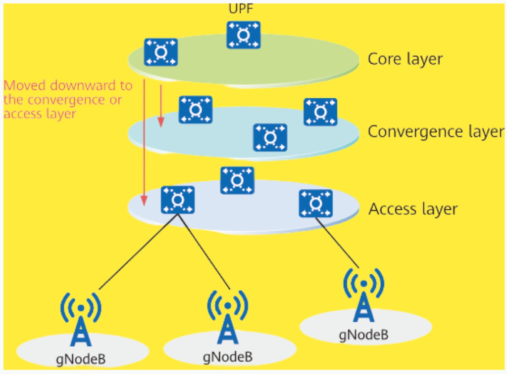
In 5G networks, one of the key strategies to reduce end-to-end (E2E) latency is the downward deployment of core network gateways. This approach involves moving the gateways closer to the base stations, typically to the aggregation or access layers of the network. By doing so, the distance that signals must travel is shortened, reducing both the optical fiber transmission delay and the number of forwarding hops, which in turn decreases the overall communication latency.
Downward Deployment of Core Network Gateways
- Reduced Transmission Distance: By positioning gateways closer to the edge, the distance between the source (e.g., a user’s device) and the destination (e.g., a friend’s device) is minimized. This reduces the time data packets take to traverse the network.
- Lower Latency: Shorter distances and fewer route hops directly contribute to lower E2E latency, which is crucial for time-sensitive services like URLLC (Ultra-Reliable Low-Latency Communication).
- Cost-Effective Edge Computing: By deploying gateways closer to the edge (e.g., 50 km away from the core network), the need for extensive edge computing resources can be minimized while still achieving the desired latency targets.

Example:
Consider making a call to a friend. In a traditional setup, data packets would need to travel through a central, upstream gateway before reaching your friend’s device, introducing significant delay. With a downward-deployed gateway, these packets can be forwarded locally, drastically reducing the latency.
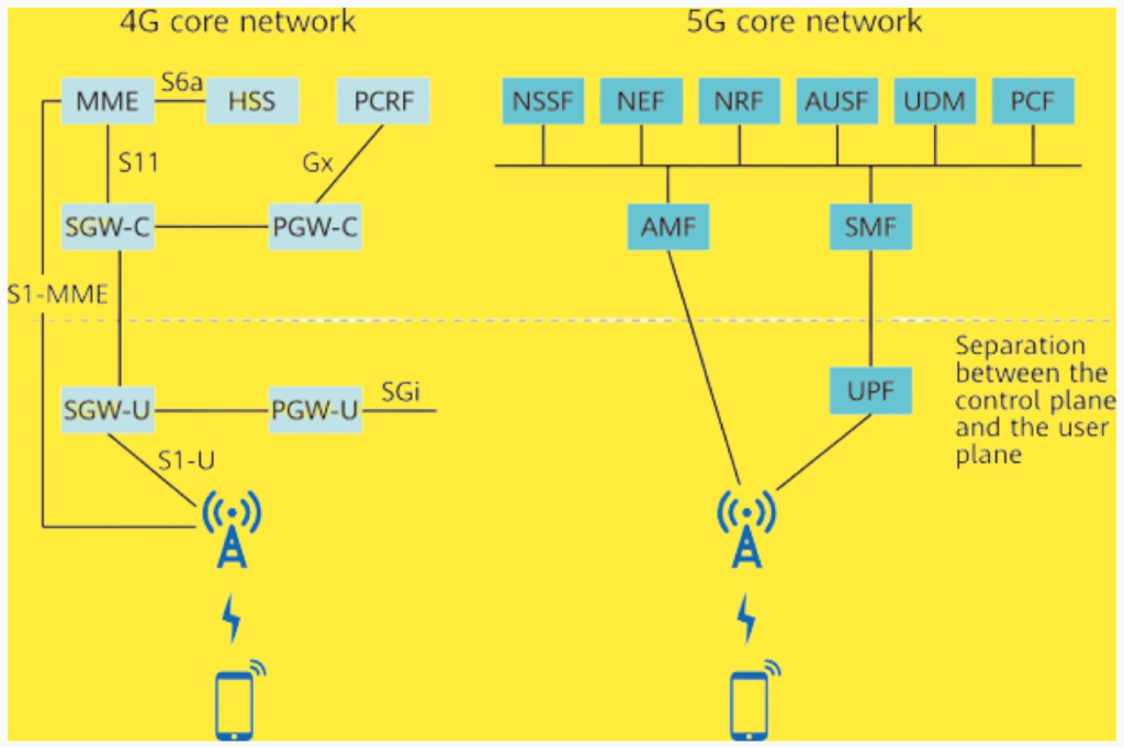
Control and User Plane Separation (CUPS):
This downward movement of core network gateways is closely related to the concept of CUPS in 5G. CUPS separates the control functions (like charging, access control, and mobility management) from the user plane. The control functions remain centralized in core equipment rooms or data centers, while the user planes are distributed closer to the network’s edge. This distribution enhances service performance but also increases the complexity of network interactions.
Network Architecture:
To manage this increased complexity, 5G redefines the signaling processes between network entities, ensuring efficient communication even as the network architecture becomes more distributed. This balance allows 5G networks to maintain high performance while managing the growing demand for low-latency, high-reliability services.

Functional units.
| Functional Unit | Full Spelling |
|---|---|
| AMF | Access and mobility management function |
| SMF | Session management function |
| AUSF | Authentication server function |
| NSSF | Network slice selection function |
| NEF | Network exposure function |
| NRF | Network repository function |
| PCF | Policy control function |
| UDM | Unified data management |
| AF | Application function |
| UPF | User plane function |
| DN | Data network |
Network Slicing in 5G
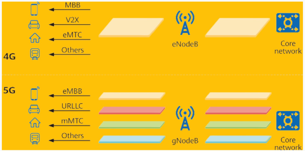
In 4G, mobile networks were primarily focused on providing services for mobile phones. However, with the advent of 5G, mobile networks need to support a wider range of service scenarios, such as enhanced mobile broadband (eMBB), massive Internet of Things (IoT), and mission-critical IoT. These diverse scenarios come with varying requirements for aspects like mobility, security, latency, and reliability.
Challenges in 5G:
As 5G networks support more services, the transport network faces an increased risk of short-term congestion, leading to uncontrollable end-to-end (E2E) latency and unreliable service delivery. This can be particularly problematic for services that require ultra-low latency and high reliability, such as URLLC (Ultra-Reliable Low-Latency Communication).
Introduction of Network Slicing:
To address these challenges, 5G introduces the concept of network slicing. Network slicing allows a single physical network to be divided into multiple virtual sub-networks, or “slices,” each tailored to meet the specific requirements of different service scenarios. By logically isolating URLLC services from other services, network slicing ensures that E2E latency is controlled and reliability is maintained.
Types of Network Slices:
5G defines different types of network slices for its three major service scenarios:
- eMBB Slice: For high-speed mobile broadband services.
- mIoT Slice: For massive IoT connections with efficient data handling.
- URLLC Slice (Slice ID 2): For ultra-reliable and low-latency communications.
Within each slice type, further subdivision into sub-slices is possible based on specific service needs. For example, within a URLLC slice, there can be sub-slices dedicated to autonomous driving, telemedicine, or other mission-critical services, each with its own set of resources and performance criteria.
By leveraging network slicing, 5G networks can efficiently manage resources, ensuring that critical services like URLLC receive the necessary prioritization to meet stringent performance requirements.

In slicing scenarios, resources can be reserved for slice groups. In this case, high-reliability services are configured by the core network to run on the corresponding slices, guaranteeing high-reliability services. The minimum and maximum RB resource percentages can be configured for resource division.

References.
- 3GPP TS 22.104, Service requirements for cyber-physical control applications in vertical domains; Stage 1 (Release 17).
- 3GPP TS 23.203, Policy and charging control architecture (Release 17).
- 3GPP TR 25.913, Requirements for Evolved UTRA (E-UTRA) and Evolved UTRAN (E-UTRAN) (Release 9).
- 3GPP TS 38.214, NR; Physical layer procedures for data (Release 16).
- 3GPP TS 22.261, Service requirements for the 5G system; Stage 1 (Release 17).
- 3GPP TS 38.211, NR; Physical channels and modulation (Release 16).
- Scheduling. Feature Parameter Description, Huawei Technologies Co., Ltd., LTE eRAN17.1.
- 3GPP TS 38.212, NR; Multiplexing and channel coding (Release 15).
- 3GPP TS 38.213, NR; Physical layer procedures for control (Release 16).
- 3GPP TS 38.323, NR; Packet Data Convergence Protocol (PDCP) specification (Release 16).
- 3GPP TS 38.331, NR; Radio Resource Control (RRC) protocol specification (Release 16).
- 3GPP TR 38.913, Study on Scenarios and Requirements for Next Generation Access Technologies (Release 16).
- URLLC. Feature Parameter Description, Huawei Technologies Co., Ltd., 5G RAN5.1.
- Short TTI. Feature Parameter Description, Huawei Technologies Co., Ltd., LTE eRAN17.1.
- Air Interface Latency Optimization. Feature Parameter Description, Huawei Technologies Co., Ltd., LTE eRAN17.1.