Prerequisites of this article to understand URLLC completely.
- What is URLLC? Basic and Technical Understanding.
- What Are the Requirements for Latency and Reliability on the 4G RAN Side?
- What Network Deployment Solutions Are Available for URLLC?
URLLC Solutions on the 5G RAN Side.
At the beginning of 5G system design, each protocol layer on the user plane was optimized for URLLC.

1. Low-Latency Technologies.
Low-latency technologies are mainly applied at the physical layer, MAC layer, and RLC/PDCP layer. Table below describes related technologies.
Table below Low-latency technologies.
| User-Plane Protocol Layer | Technology |
|---|---|
| Physical layer | Self-contained slot |
| Mini-slot | |
| Scalable numerology | |
| Channel coding with better performance | |
| MAC layer | Uplink grant-free scheduling |
| Downlink preemption scheduling | |
| Asynchronous HARQ | |
| HARQ enhancement | |
| RLC/PDCP layer | PDCP out-of-order delivery |
Physical Layer.
In 4G, uplink and downlink slots are strictly separated, meaning that each slot is exclusively used for either uplink or downlink transmission. However, 5G introduces a more flexible approach by incorporating mixed slots, as defined in 3GPP TS 38.213. These mixed slots can contain a combination of downlink symbols, uplink symbols, and “flexible” symbols within the same slot. This flexibility allows for different slot formats, some of which are designed specifically as self-contained slots.
Self-Contained Slots in 5G.
Self-contained slots in 5G are a significant advancement, designed to enhance the network’s ability to meet ultra-low latency requirements. A self-contained slot includes both downlink and uplink symbols, allowing for the transmission of both data and control signals within the same slot. This configuration reduces the uplink/downlink feedback delay and the scheduling delay, which are crucial for services that require minimal latency, such as autonomous driving or industrial automation.
Below Figures illustrate the structure of self-contained slots:
DL-Dominant Slot:
Primarily used for downlink data transmission. Most symbols in the slot are dedicated to downlink data, but a few symbols are reserved for uplink control signals, such as HARQ feedback for downlink data or Sounding Reference Signals (SRSs). The presence of uplink control symbols within the slot helps to shorten the delay for downlink HARQ feedback, making the communication process more efficient.

UL-Dominant Slot:
Primarily used for uplink data transmission. Most symbols in this slot are allocated to uplink data, with a few symbols set aside for downlink control signals. These control signals may include uplink scheduling indications sent via the Physical Downlink Control Channel (PDCCH). By including these control signals within the slot, the uplink scheduling delay is reduced, which is particularly beneficial for applications that demand quick response times.

Benefits of Self-Contained Slots
The introduction of self-contained slots in 5G significantly improves the network’s efficiency in handling latency-sensitive applications. By combining both uplink and downlink transmissions within a single slot, the network can quickly adapt to changing conditions and provide faster feedback, which is essential for maintaining the reliability and low latency required by advanced 5G services. This innovation is a key factor in enabling the ultra-reliable low-latency communication (URLLC) that 5G promises.
Mini-Slot
In 4G and 5G, a slot typically serves as the basic unit for scheduling data transmission, which involves 14 consecutive OFDM symbols in the time domain. In 4G, the subcarrier spacing (SCS) is fixed at 15 kHz, leading to a consistent scheduling interval of 1 ms. However, in 5G, various SCS options are available, allowing for more flexible scheduling intervals. Despite this flexibility, even with a 30 kHz SCS (which corresponds to a 0.5 ms interval), the scheduling might still fall short of meeting the extremely low latency demands of ultra-reliable low-latency communication (URLLC) services.
Mini-Slot for Lower Latency in 5G
To address the stringent latency requirements of URLLC, the concept of the mini-slot was introduced in 5G, particularly leveraging Type B resource allocation. Unlike traditional slots, which always span 14 symbols, a mini-slot can consist of fewer symbols, offering a finer granularity for scheduling. This approach, also known as Non-Slot-based Scheduling, allows for scheduling with a smaller number of OFDM symbols (fewer than 14), and the start position of this scheduling can be flexibly adjusted, independent of the conventional slot boundaries.
In 3GPP Release 15, mini-slots can be configured with different symbol counts, specifically supporting configurations with 2, 4, or 7 symbols. This flexibility enables faster data transmission and response times, which are critical for the ultra-low latency requirements in scenarios like industrial automation, autonomous vehicles, and other real-time applications.
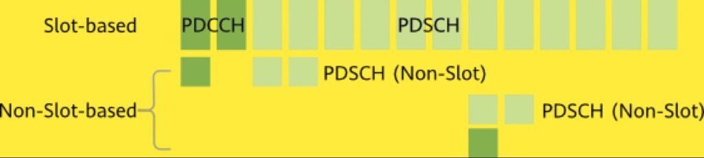
Advantages of Mini-Slots
- Reduced Latency: By minimizing the number of symbols in a scheduling unit, mini-slots help reduce the overall transmission delay, which is essential for URLLC services.
- Flexible Scheduling: Mini-slots do not need to align with traditional slot boundaries, allowing more precise control over when transmissions occur. This flexibility is particularly beneficial in environments where quick responses are needed.
- Adaptability: With various SCS options and the ability to configure mini-slots with different numbers of symbols, 5G networks can adapt to a wide range of latency and throughput requirements, making it suitable for diverse applications.
Scalable numerology.
In 4G, the subcarrier spacing (SCS) is fixed at 15 kHz, which means that the network operates with a consistent time and frequency structure. This limitation constrains the flexibility and adaptability of the network, especially when dealing with varying frequency bands and latency requirements.

SCS in 5G
5G introduces the concept of scalable numerology, allowing for different SCSs depending on the frequency band, as defined in 3GPP TS 38.211. The supported SCSs vary as follows:
- Below 1 GHz: 15 kHz and 30 kHz
- 1 GHz to 6 GHz: 15 kHz, 30 kHz, and 60 kHz
- 24 GHz to 52.6 GHz (mmWave): 60 kHz and 120 kHz
Impact of Scalable Numerology
In 4G, the time unit used for data scheduling is a subframe with a fixed length of 1 ms. In contrast, 5G uses a slot as the time unit for scheduling, but with a twist: while a slot always consists of 14 symbols, the actual length of each symbol varies depending on the SCS. This variation allows the network to adapt the scheduling interval based on the specific requirements of different services and frequency bands.
- 15 kHz SCS: One slot lasts 1 ms, equivalent to the 4G subframe.
- 30 kHz SCS: One slot lasts 0.5 ms, cutting the scheduling time in half compared to 15 kHz.
- 60 kHz SCS: One slot lasts 0.25 ms, further reducing latency.
- 120 kHz SCS: One slot lasts 0.125 ms, offering even shorter scheduling intervals, particularly useful in high-frequency bands like mmWave.
Advantages of Scalable Numerology
- Latency Reduction: As the SCS increases, the length of each OFDM symbol decreases, leading to a shorter slot duration. This results in faster scheduling intervals and reduced latency, which is critical for ultra-low latency applications like autonomous driving and industrial automation.
- Adaptability: The ability to adjust the SCS allows 5G networks to efficiently handle diverse use cases across different frequency bands, from broad coverage in lower frequencies to high-capacity, low-latency applications in mmWave bands.
- Optimized Performance: Scalable numerology helps optimize network performance by matching the numerology to the specific propagation characteristics of the frequency band, improving overall network efficiency and user experience.
Channel coding with better performance
In 5G, the polar code applies to control channels, and the low density parity check (LDPC) code applies to data channels. The 5G coding schemes deliver better decoding performance, lower processing latency, and higher reliability than 4G coding schemes.
Table below shows comparison between 4G and 5G channel coding schemes.
| Comparison Between 4G and 5G Channel Coding Schemes | Control Channel | Data Channel |
|---|---|---|
| 5G | Polar code | LDPC code |
| 4G | Convolutional code | Turbo code |
| Comparison | The polar code requires a lower signal-to-noise ratio (SNR) under the same block error rate (BLER). | The LDPC code is more suitable for transmission of large data blocks and allows for faster decoding (thanks to the support for parallel decoding) and lower power consumption. |
MAC Layer
Uplink Grant-Free Scheduling in 5G
Common Uplink Data Transmission:
In traditional uplink data transmission, a User Equipment (UE) must first request scheduling resources from the base station before it can transmit data. This process is similar to shipping a package:
- The UE (sender) notifies the base station (express company) that it needs to transmit data (send a scheduling request, SR).
- The base station allocates resources (arranges a courier) for the transmission.
- The UE transmits the data (package).
- After receiving the data, the base station sends feedback (acknowledgement of package receipt). (HARQ Feedback)

The time taken for requesting and allocating resources (t1 and t2) is a significant part of the total transmission time, which can cause delays. Figure below provides an example of common SR-based scheduling in 5G, where the average duration from the arrival of uplink packets to data transmission of the UE is 15 ms.

Uplink Preallocation in 4G:
To reduce latency, 4G introduced uplink preallocation, where the base station periodically allocates resources to the UE, even if the UE hasn’t sent an SR. This reduces the waiting time for resource allocation. Semi-persistent scheduling was also introduced, where resources are allocated once and can be used periodically, reducing the need for repeated scheduling requests.
However, in dense networks with many UEs, this can lead to resource wastage since not all UEs may use the allocated resources.
Uplink Grant-Free Scheduling in 5G:
3GPP TS 38.214 introduces uplink grant-free scheduling in 5G, allowing resources to be reserved and used without the need for repeated SRs. This reduces latency and resource wastage. Uplink grant-free scheduling is divided into two types:
Uplink Grant Type 1:
- Common parameters are configured through RRC signaling.
- The UE uses the granted resources to transmit data.
- Suitable for static scenarios with periodic services.
- Requires reconfiguration for changes, causing delays.
Uplink Grant Type 2:
- Common parameters are also configured through RRC signaling, but activation/deactivation is indicated through DCI.
- The UE transmits data only after receiving DCI.
- Suitable for mobile scenarios with periodic services.
- Has low switching delay due to direct MAC layer delivery.


Contention-Based Transmission:
Uplink grant-free scheduling is contention-based, meaning that multiple UEs might compete for the same resources. If resources are insufficient, conflicts may occur, leading to failed data decoding and the need for retransmission.
Optimizations in 3GPP Release 16:
To address this issue, 3GPP Release 16 optimizes the retransmission scheme to support K repetitions in the time domain or frequency domain. Specifically, a UE sends n (n ≤ K) data copies in the time or frequency domain, and each copy has a pointer pointing to another copy. If data conflicts occur during decoding, the gNodeB can search for the corresponding data copy based on the pointer to assist in decoding the conflicting data, as shown in Figure 1 and Figure 2.
Take “K” repetitions in the frequency domain as an example. Assume that UE1 sends copies (d1) of data 1 by using two different PRBs (F1 and F2), and UE2 sends a copy (d2) of data 2 by using one PRB (F1). In this case, the gNodeB will receive copies of both data 1 and data 2 in F1, that is, the PRB resource conflict occurs. As a result, the gNodeB fails to decode the data received in F1. However, if the gNodeB successfully decodes the other copy of d1 sent in F2, then it can identify d1’s copy sent in F1 through the pointer and resolve the conflict through interference cancellation.


Downlink preemption scheduling
In 5G networks, downlink preemption scheduling is a technique used to manage limited air interface resources efficiently, especially when handling URLLC (Ultra-Reliable Low-Latency Communication) services, which require ultra-low latency. When resources are scarce, and URLLC data needs to be transmitted, this method allows URLLC services to take priority over eMBB (enhanced Mobile Broadband) services.

Here’s how it works:
- Sufficient Resources: If there are enough available resources, the base station allocates these idle resources to the URLLC user, ensuring timely transmission without affecting the eMBB user.
- Insufficient Resources: When resources are not sufficient, the base station issues a preemption indication (PI) to the eMBB user through the PDCCH (Physical Downlink Control Channel) DCI (Downlink Control Information). This PI informs the eMBB user that some of its allocated resources will be taken over by the URLLC service. The base station then reallocates these resources to the URLLC user, enabling the URLLC data packets to be transmitted immediately.
This approach ensures that URLLC services can meet their stringent latency requirements, even when competing with other services for network resources.
Asynchronous HARQ.
Asynchronous HARQ (Hybrid Automatic Repeat Request) is a crucial mechanism in 5G networks that enhances the reliability of data transmission by ensuring that information is correctly delivered between the sender and receiver. If the data is not delivered correctly, the sender retransmits the information, maintaining its integrity.
In 5G, asynchronous adaptive HARQ is employed for both uplink and downlink transmissions, unlike in 4G where asynchronous adaptive HARQ was used only for the downlink, and synchronous adaptive or non-adaptive HARQ was used for the uplink. This shift to asynchronous HARQ in 5G allows for a more flexible and dynamic assignment of retransmission intervals, which is essential for meeting the stringent low-latency requirements of modern applications.
Additionally, 5G networks support up to 16 HARQ processes per entity, as specified in 3GPP TS 38.331, compared to a maximum of eight in 4G. This increase in the number of parallel HARQ processes allows for faster data processing and reduced latency, which is critical for the performance of high-demand services like URLLC (Ultra-Reliable Low-Latency Communication).
HARQ comparison between 4G and 5G
| HARQ Mechanism | Time | Adaptive Mode | Maximum Number of HARQ Processes |
|---|---|---|---|
| 5G uplink/downlink HARQ | Asynchronous | Adaptive | 16 |
| 4G uplink HARQ | Synchronous | Adaptive/Non-adaptive | 8 |
| 4G downlink HARQ | Asynchronous | Adaptive | 8 |
HARQ enhancement.
In 5G, HARQ (Hybrid Automatic Repeat Request) has been significantly enhanced to support ultra-low latency and high-reliability communication, which are critical for applications like URLLC (Ultra-Reliable Low-Latency Communication). One of the key enhancements is the introduction of short PUCCH (Physical Uplink Control Channel) formats, which allow for faster HARQ and CSI (Channel State Information) feedback, making them more suitable for low-latency service scenarios.
Comparison between different PUCCH formats
| PUCCH Format | Format Type | Number of Occupied Symbols | Number of Occupied PRBs per UE | Transmitted Data Volume | Application Scenario | Carried Information | Support of UE CDM |
|---|---|---|---|---|---|---|---|
| Format 0 | Short format | 1 to 2 | 1 | ≤ 2 bits (small data volume) | Ultra-low latency | HARQ/SR | Supported |
| Format 1 | Long format | 4 to 14 | 1 | ≤ 2 bits (small data volume) | Coverage improvement | HARQ/SR | Supported |
| Format 2 | Short format | 1 to 2 | 1 to 16 | > 2 bits (large data volume) | Ultra-low latency | HARQ/SR/CSI | Not supported |
| Format 3 | Long format | 4 to 14 | 1 to 6, 8 to 10, 12, 15, 16 | > 2 bits (large data volume) | Coverage improvement | HARQ/SR/CSI | Not supported |
| Format 4 | Long format | 4 to 14 | 1 | > 2 bits (medium data volume) | Coverage improvement | HARQ/SR/CSI | Supported |
PUCCH Formats in 5G
Compared to 4G, 5G offers five different PUCCH formats, with the addition of short formats (1 to 2 symbols). These short PUCCH formats enable quicker transmission of control information, including HARQ feedback, thereby reducing latency. This is particularly beneficial in scenarios that require ultra-low latency, such as real-time communication or mission-critical applications.
HARQ Feedback Timing and the Challenge
In 3GPP Release 15, a 5G slot can accommodate one or two PUCCHs, with at least one being in the short format. However, HARQ feedback can only be transmitted on one of these PUCCHs within the same slot. The specific timing for the PUCCH transmission is usually indicated by the PDSCH-to-HARQ-feedback-timing-indicator IE, which is included in the last scheduled PDSCH (Physical Downlink Shared Channel).
A potential challenge arises when the HARQ feedback is indicated to be transmitted on the second PUCCH in the slot. If the last PDSCH specifies the second PUCCH for HARQ feedback, the feedback transmission for earlier PDSCHs has to wait until the end of the slot. This waiting time introduces additional delay, especially in scenarios where the SCS (Subcarrier Spacing) is relatively small, making the feedback process slower.
Solution in 3GPP Release 16
To mitigate the delay issue, 3GPP Release 16 introduces a mechanism that allows simultaneous transmission of HARQ feedback on two PUCCHs within the same slot. This solution leverages a sub-slot structure, which includes several symbols, to distinguish between different PUCCH resources used for transmitting separate HARQ feedback information.
Furthermore, two distinct HARQ codebooks are defined in the 3GPP specifications. These codebooks separately indicate the acknowledgment of the PDSCHs that are mapped to PUCCH 1 and PUCCH 2. This distinction allows for more efficient and timely HARQ feedback, reducing the overall latency in the network.
.")
.")
This enhancement is particularly important for maintaining low latency in high-demand scenarios, ensuring that 5G networks can meet the stringent requirements of applications that rely on quick and reliable data transmission.
RLC/PDCP Layer.
PDCP out-of-order delivery.
In 4G, the reordering of data packets caused by HARQ operations at the MAC layer introduces delays at the PDCP (Packet Data Convergence Protocol) layer, which negatively impacts latency. Specifically, when packets are delivered to the RLC (Radio Link Control) layer out of order, the RLC layer must wait until all earlier packets have arrived before forwarding them to the PDCP layer. This waiting period introduces delays because the PDCP layer can only begin decryption and further processing once it has received all the necessary packets in the correct order.

Issue with Reordering in 4G
For example, if four data packets are sent, but due to HARQ retransmissions, packets 3 and 4 arrive at the RLC layer before packet 2, the RLC layer holds onto packets 3 and 4 until packet 2 is received. Only after receiving packet 2 can the RLC layer deliver packets 2, 3, and 4 to the PDCP layer for processing. This introduces a significant delay because the PDCP layer must wait for the missing packets before it can proceed.
5G Enhancement: Reordering at the PDCP Layer
To address this issue, 3GPP TS 38.323 introduces a key improvement in 5G by moving the reordering function up to the PDCP layer. This change allows the RLC layer to deliver packets to the PDCP layer as soon as they are received, regardless of whether earlier packets have been delivered.

In 5G, when the RLC layer successfully receives any packet, it immediately passes it to the PDCP layer. The PDCP layer can then start processing (including decryption) on the packets it receives without having to wait for earlier packets to arrive. This reduces the overall waiting delay at the PDCP layer.
Example Scenario
Continuing with the previous example, in 5G, if packets 3 and 4 arrive before packet 2, the RLC layer can immediately deliver packets 3 and 4 to the PDCP layer. The PDCP layer can start decrypting these packets without waiting for packet 2. If packet 2 eventually arrives, it can be processed afterward. This method significantly reduces the delay, especially in scenarios where packet delivery is not perfectly sequential.
2. High-Reliability Technologies.
High-reliability technologies are mainly used at the physical and PDCP layers. Table below describes related technologies.
Table High-reliability technologies.
| User-Plane Protocol Layer | Technology |
|---|---|
| Physical layer | Intra-/Inter-slot repeated PUSCH transmission |
| Compact DCI | |
| Control channel enhancement | |
| Low-bit-rate transmission | |
| RLC/PDCP layer | Data replication at the PDCP layer |
Physical Layer
Intra-/Inter-slot repeated PUSCH transmission
Inter-Slot Repeated PUSCH Transmission
In 3GPP Release 15, a method called inter-slot repeated PUSCH transmission was introduced to improve the reliability of uplink transmissions. With this approach, the same PUSCH (Physical Uplink Shared Channel) data is repeatedly sent over continuous slots using the same time-frequency resources. By doing this, the chances of successfully transmitting the data are increased, especially in challenging network conditions.

Intra-Slot Repeated PUSCH Transmission
In 3GPP Release 16, further enhancements were made with the introduction of intra-slot repeated PUSCH transmission. This method allows for the PUSCH to be transmitted multiple times within a single slot, which is divided into smaller segments called mini-slots. These repetitions can be either grant-based or grant-free, and they provide an additional boost to reliability by allowing multiple chances for the data to be correctly received within the same slot.

Compact DCI
To meet the ultra-high reliability demands of URLLC services in 5G, 3GPP Release 16 introduced two specialized DCI (Downlink Control Information) formats known as compact DCIs: DCI format 0_2 and DCI format 1_2. These formats are optimized to carry fewer bits by minimizing the size of various fields, which enhances reliability.

For example, in frequency-domain scheduling, these compact DCIs use RBG (Resource Block Group) allocation instead of per RB (Resource Block) allocation, reducing the amount of scheduling information that needs to be transmitted. This efficiency lowers the DCI load on the PDCCH (Physical Downlink Control Channel), decreases the DCI code rate, and improves fault tolerance, making it possible to achieve the extremely high reliability of 99.999% required for URLLC, even in challenging signal conditions (SINR > -3 dB).


Control channel enhancement.
Control Channel Enhancement
In 5G, the PDCCH (Physical Downlink Control Channel) uses Control Channel Elements (CCEs) as its basic units. The number of CCEs allocated to a PDCCH is called the aggregation level, and it directly influences the channel’s demodulation performance. A higher aggregation level is used when the DCI (Downlink Control Information) payload is larger or the radio channel quality is lower, ensuring better performance.
In 4G, a PDCCH can use up to 8 CCEs. However, in 5G, 3GPP Release 16 increases this limit to 16 CCEs per PDCCH. This enhancement provides more resources to improve demodulation, which is crucial for maintaining reliable transmission, especially in challenging conditions. The increased aggregation levels offer more flexibility to ensure that the control channel can meet the rigorous demands of 5G services.
| Aggregation Level | Number of CCEs |
|---|---|
| 1 | 1 |
| 2 | 2 |
| 4 | 4 |
| 8 | 8 |
| 16 | 16 |
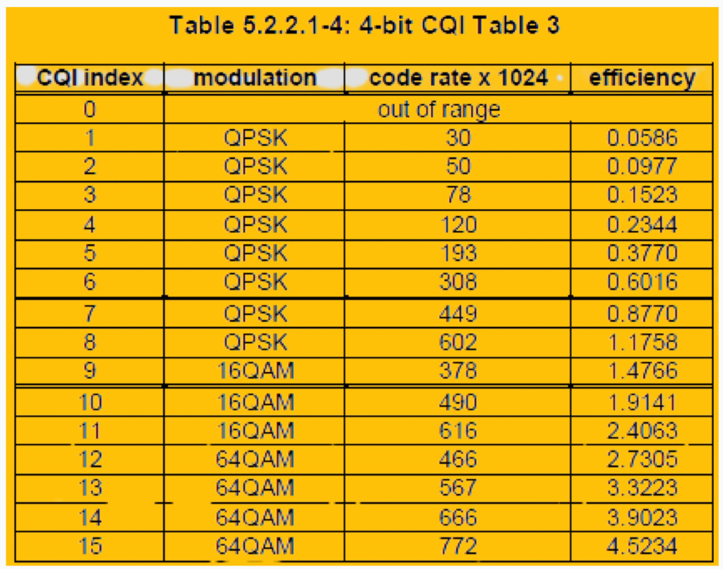
Low-Bit-Rate Transmission in 5G URLLC
In digital communications, increasing the modulation order improves spectrum efficiency but also raises the Block Error Rate (BLER). The CQI (Channel Quality Indicator) and MCS (Modulation and Coding Scheme) tables used in 4G are not sufficient to achieve the high reliability required by 5G URLLC (Ultra-Reliable Low-Latency Communication) services, which target a BLER of 10-5 in a single transmission.
To address this, 3GPP TS 38.214 introduces specific MCS index and CQI tables for 5G URLLC, designed to meet a 99.999% reliability requirement:
- Lower Modulation Order: For the same MCS index, URLLC uses a lower modulation order compared to eMBB (enhanced Mobile Broadband). For example, with MCS index 10, URLLC uses a modulation order of 2, while eMBB uses 4. This conservative approach reduces the likelihood of errors during modulation and demodulation, enhancing reliability.
- Lower Target Code Rate: Similarly, URLLC employs a lower target code rate to improve its anti-interference capability. For instance, with MCS index 10, URLLC might use a target code rate of 308, whereas eMBB uses 340/658. This lower code rate further ensures reliable data transmission under the same channel conditions by prioritizing error correction over speed.

This approach allows 5G URLLC to maintain its stringent reliability standards, even in challenging environments.
Data Replication at the PDCP Layer in 5G.
In 5G, data replication at the PDCP (Packet Data Convergence Protocol) layer is used to enhance transmission reliability, especially in scenarios involving carrier aggregation (CA) or dual connectivity (DC). This feature allows a single data packet to be duplicated and transmitted across different radio interface resources, providing diversity gains at the receiver.
Here’s how it works:
- Replication Process: A data packet, such as “Packet A,” is replicated at the PDCP layer into multiple copies.
- Mapping to Logical Channels: These replicated copies are then mapped to different logical channels, which correspond to different RLC (Radio Link Control) entities.
Resource Allocation:
- In CA scenarios, these logical channels belong to the same MAC (Medium Access Control) entity.
- In DC scenarios, they belong to different MAC entities, enabling the use of diverse transmission paths.
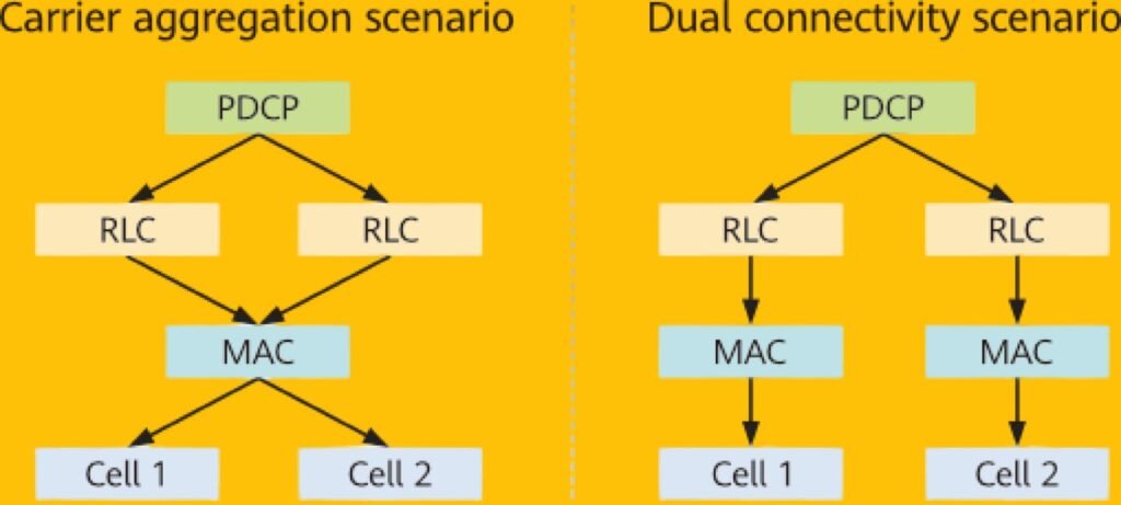
This approach leverages multiple radio resources to increase the chances of successful data delivery, improving overall transmission reliability.
References.
- 3GPP TS 22.104, Service requirements for cyber-physical control applications in vertical domains; Stage 1 (Release 17).
- 3GPP TS 23.203, Policy and charging control architecture (Release 17).
- 3GPP TR 25.913, Requirements for Evolved UTRA (E-UTRA) and Evolved UTRAN (E-UTRAN) (Release 9).
- 3GPP TS 38.214, NR; Physical layer procedures for data (Release 16).
- 3GPP TS 22.261, Service requirements for the 5G system; Stage 1 (Release 17).
- 3GPP TS 38.211, NR; Physical channels and modulation (Release 16).
- Scheduling. Feature Parameter Description, Huawei Technologies Co., Ltd., LTE eRAN17.1.
- 3GPP TS 38.212, NR; Multiplexing and channel coding (Release 15).
- 3GPP TS 38.213, NR; Physical layer procedures for control (Release 16).
- 3GPP TS 38.323, NR; Packet Data Convergence Protocol (PDCP) specification (Release 16).
- 3GPP TS 38.331, NR; Radio Resource Control (RRC) protocol specification (Release 16).
- 3GPP TR 38.913, Study on Scenarios and Requirements for Next Generation Access Technologies (Release 16).
- URLLC. Feature Parameter Description, Huawei Technologies Co., Ltd., 5G RAN5.1.
- Short TTI. Feature Parameter Description, Huawei Technologies Co., Ltd., LTE eRAN17.1.
- Air Interface Latency Optimization. Feature Parameter Description, Huawei Technologies Co., Ltd., LTE eRAN17.1.
Discover more from PAKTECHPOINT
Subscribe to get the latest posts sent to your email.