In this article we are going to discuss about the differences between 4G and 5G coverage KPIs, differences between 4G and 5G coverage optimization, analyze the coverage and overlapping coverage problems and optimize the main factors that cause overlapping coverage problems.
1. Overview of 5G NR Coverage Analysis.
Key Indicators for NR Coverage.
Similar to LTE, the key indicators related to coverage in 5G are RSRP and SINR. However, the types of RSRP/SINR in 5G are different from LTE. The LTE CRS function, in NR, is divided into two measurement quantities: SSB and CSI-RS. Correspondingly, the SS-RSRP/SINR reflects the coverage and access capability of the broadcast channel, and the CSI RSRP/SINR reflects the capability of the traffic channel.
Coverage measurement results defined in 5G:

Based on the beam definition, under the same coverage point: The values of SS RSRP,
CSI RSRP, and PDSCH RSRP may vary greatly. Currently, the CSI RSRP protocol
defines a maximum of 32 beams. The mapping between SS RSRP and CSI RSRP is also
defined by protocols. Denser the SSB and CSI beam, closer the value of SS RSRP and
CSI RSRP.
SS-RSRP / SS-SINR
SS-RSRP (SS reference signal received power), is defined as the linear average over the power contributions of the resource elements that carry downlink secondary synchronization signals (SS). In the SSB measurement configuration period. The measurement status of the UE includes the RRC_IDLE state, RRC-INACTIVE state, and RRC_CONNECTED state.
SS-SINR (SS signal-to-noise and interference ratio): is defined as the power of the RE carrying the secondary synchronization signal in the primary serving cell, divided by the noise and interference power within the same frequency bandwidth.
SS RSRP and SINR: Measured on the synchronization channel, which is affected by network planning (topology, RF parameters), and beam scanning, can represent the coverage status of the cell.
For details, refer 38.215 5.1 UE measurement capabilities.
SS-RSRQ
SS-RSRO(SS reference signal received quality)
It is defined as the ratio of NxSS-RSRP/(NR carrier RSSI) in the protocol.
N is the number of resource blocks in the NR carrier RSSI measurement bandwidth. The
measurements in the numerator and denominator shall be made over the same set of resource blocks.
RSSI is referred to the linear average of the total received power in certain OFDM symbols of measurement time resource(s), in the measurement bandwidth. The received power of all RE in the measurement bandwidth of each resource block is accumulated, including useful signals, interference, and thermal noise. Then, average linearly over the OFDM symbol which is time. The UE measurement status includes RRC_IDLE, RRC-INACTIVE, and RRC_CONNECTED.
For details, refer 38.215 5.1 UE measurement capabilities.

CSI-RSRP/CSI-SINR
CSI-RSRP (CSI reference signal received power): is defined as the linear average power of the CSI reference signal of the RE on the CSI measurement frequency bandwidth configured under different antenna ports. Applicable for UE is the RRC_CONNECTED state.
CS-SINR (CSI signal-to-noise and interference ratio): is defined as the power of the RE carrying the CSI RS signal, divided by the interference noise power on the corresponding bandwidth. CSI-RSRP and SINR: Indicator for user level, which is affected by user distribution and cell load. It reflects the service capability of the network to user.
For details, refer 38.215 5.1 UE measurement capabilities.
CSI-RSRQ
CS-RSR (CSI reference signal received quality)
It is defined as the ratio of NxCSI-RSRPl(NR carrier RSSI) in the protocol.
N is the number of resource blocks in the CSI-RSSI measurement bandwidth. The numerator and denominator are obtained from the same resource block.
The RSSI is the linear average of the total received power on the measurement time and the measurement bandwidth of a specified OFDM symbol. The received power of all RE in the measurement bandwidth of each resource block is accumulated, including useful signals, interference and thermal noise. Then, average linearly over the OFDM symbol which is time. The UE measurement status includes the RRC_CONNECTED state.
For details, see 38.215 5.1 UE measurement capabilities.

Objective of Coverage Optimization.
NR coverage optimization has the following objectives:
- Optimize the signal coverage to ensure the RSRP/SINR of the target area meets the network coverage standards.
- Resolve the RF problems found during the drive test such as weak coverage, overshoot coverage, ping-pong handover, inappropriate handover zone, and interference.
- Optimize the coverage area and handover zone based on the throughput.
The recommended coverage optimization standards for different target scenarios:

Overall objective of coverage optimization:
Ensure a reasonable SSB coverage, reduce ping-pong handovers, reduce interference from neighboring cells, optimize SS SINR, and ensure user access.
Coverage optimization target achievement does not mean the achievement of target throughput, but also needs to consider environment and Rank optimization.
Differences between LTE and NR Coverage.
In NR, the measure quantities include both SSB and CSI-RS, therefore, SS RSRP and CSI RSRP need to be considered independently for NR coverage evaluation. SS RSRP is used for the coverage and access capability of the broadcast channel, and CSI RSRP is used for the service channel quality.
Because of the beamforming, in the same coverage area: The value of SS RSRP, CSI RSRP,
and PDSCH RSRP may be different. the SSB and CSL-RS use static beams. PDSCH uses
dynamic beams (SRSs and PMls).


NR Broadcast Beam Scenarios.

NR broadcast beams can be configured based on scenario-specific configurations,
whereas LTE broadcast channel is a wide beam.
In 5G RAN2.1, gNodeB supports 16 non-default scenarios, which can be specified by the
NRDUCellTrpBeam.CoverageScenario parameter.
The default scenario is typical 3-sector network. This scenario can be applied in square
scenarios.
The below table lists the beamwidth and tilt range supported by each RF module in the
default scenario.


Coverage scenario can be configured by using the NRDUCellTrpBeam. Coverage Scenario
parameter.
- Generally, it is recommended to set this parameter as DEFAULT, suitable for typical 3-sector network.
- When the requirements of horizontal coverage is wide, SCENARIO_1, SCENARIO_6, Or SCENARIO_12 is recommended. The cell edge UEs can obtain higher beam gains and cell edge coverage is improved.
- lf there is any fixed interference source at the cell edge, SCENARI0_2, SCENARI0_3, SCENARI0_7, SCENARI0_8, or SCENARIO_13 can be used to narrow down the horizontal coverage area and avoid the interference.
- If there is only isolated buildings, SCENARIO_4, SCENARIO_S, SCENARIO_9, SCENARIO_10, SCENARIO_11, SCENARIO_14, SCENARIO_15, Or SCENARIO_16 is recommended to provide small horizontal coverage. These scenanos are not suitable for continuous coverage.
- When there are only low-rise buildings, you can select from SCENARIO_1 to SCENARIO_5.
- When there are mid-rise buildings, you select from SCENARIO_6 to SCENARIO_11.
- When there are high-rise buildings, you can select from SCENARI0_ 12 to SCENARIO_16.
NR Broadcast Beam Tilt and Azimuth.
In NR, the tilts and azimuths of the SSB can be adjusted, to reduce the difficulty of site selection and on-site optimization.
- the granularity of the adjustment is 1°.
- In scenarios where the interference from neighboring cells is high, the tilt and azimuth can be adjusted to make the beams focus at users in the local cell. This reduces the overlapped coverage in neighboring cells.
- More beam directions can be achieved by adjusting the tilt and azimuth, meets different coverage requirements for a flexible networking
Note: If the vertical scanning range has reached the upper limit (scenario 12-16), tilt adjustment is not supported. If the horizontal scanning range has reached the upper limit (scenario 0,1,6,12), azimuth adjustment is not supported.

The adjustment of the tilt and azimuth degree is based on the parameter setting on the
GUI. Then, the parameter is substituted into the steering vector. The steering vector is
multiplied by the initial weight matrix to obtain the final steering vector, which is then sent
to the baseband part.
Note: Only the maximum adjustment capability is provided here. In actual situations, when the tilt is adjusted to a certain degree, the side lobe suppression may not be sufficient. The adjustment range varies according to the specific requirements.
If the upper side lobe meets the suppression requirement of 12 dB, the preset downtilt (6°) is used as the reference. For digital RET, the increase range is 8° and the decrease range is 3°.
The tilt adjustment range in scenarios 1 to 5 (with a vertical 3 dB beamwidth of 6°) is –2° to 9°.
The tilt adjustment range in scenarios 6 to 11 (with a vertical 3 dB beamwidth of 12°) is 0° to 6°.
SG NR Coverage Analysis Process and Operations.
Coverage Problem Analysis Process.

RSRP is the basic of the network coverage.
Its main factors are: site density, antenna height, transmit power, working frequency band, azimuth, downtilt, and handover parameters. The RSRP related to 5G coverage includes SS-RSRP and CSI-RSRP. SS-RSRP can be used for measurement evaluation in connected mode, idle mode, and inactive state. CSI-RSRP is used for measurement evaluation in connected mode. Currently, the live network uses both evaluation mode for coverage ratio.

Principles of Coverage Problem Optimization.
Principle 1: Optimize the SS RSRP/CSI-RSRP and followed by the SS SINR/CSI SINR.
Principle 2: Firstly optimize overshoot coverage and followed by overlapping coverage
Principle 3: Optimize handover Zone, control overlapping coverage and avoid ping-pong handovers.
Principle 4: Preferentially optimize the soft parameters , next, adjust hardware or site topology.
Basic Data Collection.
The initial phase of NR coverage optimization is to obtain the basic information, including:
- Planning parameters, including PCIs, PRACHs, and neighbor relations.
- Basic engineering parameters.
- Site location, longitude and latitude of the base station.
- Number of AAU channels, height, azimuth, and downtilt.
- Planned coverage distance for a cell.
- Electronic map, coverage scenario classification, etc.
- Radio parameters: Parameters related to access, reselection, handover, and power configuration.
- Cell performance statistic.
Cell performance include:
statistics: SS-RSRP, CSI-RSRP, SS-SINR, CSI-SINR, handover success rate, Cell throughput.
Coverage Related Parameters.
| Parameter Name | Parameter Function | Impact of on Network Performance | Remarks |
| Maximum cell transmit power. Max TransmitPower | Indicates the maximum transmit power of a TRP in a NR DU cell. When the duplex mode of the NR DU cell corresponding to the TRP is SUL, the TRP of the NR DU cell works only in the uplink In this case, this parameter is invalid | If this parameter is set to a small value, the coverage of the corresponding cell will be affected. If this parameter is set to a large value, the cell signal will interfere the neighbouring cells and affect the overall network performance | NSA and SA |
| Maximum SS/PBCH Power Offset: Max SsPbchPwrOttset | Indicates the maximum power offset of the cell synchronization signal and physical broadcast channel relative to the reference power after power aggregation is performed on cell synchronization signal and physical broadcast channel. The actual effective value may be lower than the configured value because of the constraints of the power aggregation capability of the intermediate frequency (IF) and radio frequency (RF) Of the power resource constraints during scheduling. | A larger value of this parameter indicates a larger coverage range of the synchronization signal and the physical broadcast channel but less available power for data channel. A smaller value of this parameter leads to the opposite effects. | NSA and SA |
| Maximum Common DCI Power Offset: MaxCommonDciPwrOffset | Indicates the maximum offset of the DCl power in common search space relative to the reference power after DCI power aggregation in the common search space of a cell is performed. The actual effective value may be lower than the f configured value because of the constraints of the power aggregation capability of the intermediate frequency (IF) and radio frequency (RF) or the power resource constraints during scheduling. | Larger the value of this parameter, larger the coverage of the DCI in the common search space, but lesser the available power for other DCI Smaller the value of this parameter, smaller the coverage range of DCI in the common search space, but more power available for other DCI. | NSA and SA |
| RMSI DCI Maximum Power Offset: MaxRmsiDciPwrOffset | Indicates the maximum offset between the transmit power of the RMSI DCI and the reference power of the cell The actual effective value may be lower than the configured value due to constraints on the RF power convergence capability or power resource constraints during scheduling. | Larger the value of this parameter, larger the power used by the cell to broadcast RMSI DCI and larger the RMSI DCI coverage, but lesser the available power for other PDCCH scheduling. Smaller the value of this parameter, smaller the power used for cell broadcast RMSI DCI transmission and smaller the cell broadcast RMSI DCI coverage, but greater the available power for other PDCCH scheduling. | SA |
| Paging DCI Maximum Power Offset: MaxPagingDciPwrOffset | Indicates the maximum offset between the transmit power of the Paging DCI and the reference power of the cell. The actual effective value may be lower than the configured value due to the constraints on the RF power convergence capability or power resource constraints during scheduling. | Larger the value of this parameter, larger the Paging DCI coverage, but lesser available power for other PDCCH scheduling. Smaller the value of this parameter, smaller the cell broadcast Paging DCI coverage, but greater the available power for other PDCCH scheduling. | SA |
| OSI DCI Maximum Power Offset: MaxOsiDciPwrOffset | Indicates the maximum offset between the transmit power of the OSI DCI and the reference power of the cell The actual effective value may be lower than the configured value due to the constraints on the RF power convergence capability or power resource constraints during scheduling. | Larger the value of this parameter, larger the cell broadcast OSI DCI coverage, but lesser the available power for other PDCCH scheduling. Smaller the value of this parameter, smaller the cell broadcast OSI DCI coverage, but greater the available power for other PDCCH scheduling. | SA |
| Maximum Dedicated DCI Power Offset: MaxDedicatedDciP wrOffset | This parameter specifies the maximum offset of the DCI power of the dedicated search space relative to the reference power after DCI power aggregation is enabled for dedicated search space in the cell. The actual effective value may be lower than the configured value due to constraints on the RF power convergence capability or power resource constraints during scheduling. | Larger the value of this parameter, larger the channel coverage of the DCI in the dedicated search space, but lesser the available power for other DCI Smaller the value of this parameter, smaller the coverage of DCl for dedicated search space, but more power available for other DCI. | NSA and SA |
| RMSI Maximum Power Offset: MaxRmsiPwrOffset | Indicates the maximum offset between the transmit power of the RMSI and the reference power of the cell. The actual effective value may be lower than the configured value due to constraints on the RF power convergence capability or power resource constraints during scheduling. | Larger the value of this parameter, larger the RMS coverage, but lesser the available power for other PDSCH scheduling. Smaller the value of this parameter, smaller the cell broadcast RMSI coverage, but more available power for other PDSCH scheduling. | SA |
| Maximum Msg2 Power Offset: MaxMsg2PwrOffset | Indicates the maximum offset of the Msg2 power relative to the reference power after Msg2 power aggregation of the cell is performed. The actual effective value may be lower than the configured value because of the constraints of the power aggregation capability of the intermediate frequency (IF ) and radio frequency (RF) or the power resource constraints during scheduling. | Larger the value of this parameter, larger the coverage area of message 2, but lesser the available power for data channel. Smaller the value of this parameter, smaller the coverage area of message 2, but more power available for data channel. | NSA and SA |
| Maximum Paging Power Offset: MaxPagingPwrOffset | Indicates the maximum offset between the power used for sending paging messages and the cell reference power The actual effective value may be lower than the configured value due to constraints on the RF power convergence capability or power resource constraints during scheduling. | larger the value of this parameter, larger the paging coverage area broadcast by the cell, but lesser the available power for other pDSCH scheduling. Smaller the value of this parameter, smaller the cell broadcast paging coverage, but more available power for other PDSCH scheduling. | SA |
| Maximum OSI Power Offset: MaxOsiPwrOffset | Indicates the maximum offset of the power used during OSI transmission relative to the reference power of the cell. The actual effective value may be lower than the configured value due to constraints on the RF power convergence capability or power resource constraints during scheduling. | Larger the value of this parameter, larger the power used by the cell broadcast OSI transmission and larger the OSI coverage area broadcasted by the cell, and lesser the available power for other PDSCH scheduling. Smaller the value of this parameter, smaller the power used for broadcasting OSI messages in a cell and smaller the OSI coverage area, but more available power for other PDSCH scheduling. | SA |
Cell reference power, ReferencePwr (dBm)=MaxTansmitPower – 10 x log(RBcell x 12)
where: MaxTransmitPower is the maximum transmit power of each channel. The unit is dBm, which can be specified by the NRDUCellTrp.MaxTransmitPower parameter.
RBcell is the number of resource block (RB) corresponding to the total bandwidth of the cell. Each RB contains 12 RE.
Calculate the power of each RE on the other channels or signals (dBm) = ReferencePwr +
PowerOffset + 10*log (RFChannelNum).
PowerOffset is the maximum power offset of each channel or signal relative to the cell reference power.
RFChannelNum is the number of physical RF channels.
Common Coverage Problem Analysis.
Weak Coverage Handling.
The RSRP in the coverage area is lower than the design target, the poor air interface quality causes bad performance of access , cell throughput and more call drops.
For weak coverage issue, following factors need to be checked:
- Device faulty, Engineering quality.
- Obstruction caused by buildings.
- Low TRP transmit power.
- Network structure.
Weak coverage can be optimized by:
- Adjust azimuth or downtilt of antenna or AAU.
- Increase the height of the antenna or AAU.
- Adjust the transmit power of the base station.
- New site or in-building system.
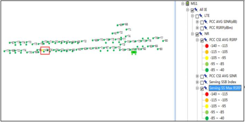
Weak coverage benchmark is based on network target. In the case above, the planned target is -95dBm @ 95%. Therefore, areas lower than the target are considered as weak coverage (yellow points).
For the key experience demo area, the coverage level is much higher.
Following solution could be taken to solve weak coverage problems:
- Adjust the antenna (or AAU) azimuth and downtilt, increase the antenna (or AAU) height, and replace the antenna with a higher gain antenna to optimize the coverage. The RET downtilt is preferred.
- If there are a large number of users in non-overlapping areas or the gap of the nonoverlapping coverage areas is big, create new base station or increase the
coverage area of the surrounding base stations to increase the depth of the overlapping coverage of two base stations to ensure a handover area. However, pay attention to the interference level after increasing the coverage range. - If there is hardware fault, rectify the fault first.
- A new base station or RRU can be used to extend the coverage area in weak coverage areas caused by concave surface, hillsides etc.
- RRU, indoor distribution system, leaky feeder, and directional antenna can be used
to solve the signal blind areas inside the elevator, tunnel, underground garage, basement, or tall building.
Overshoot Coverage.
Overshoot coverage is referred to the coverage area of some cell exceeds the planned coverage range, and cause a discontinuous dominant areas in other cells’ coverage area.
As shown in the following figure, Cell A is a overshoot coverage cell.
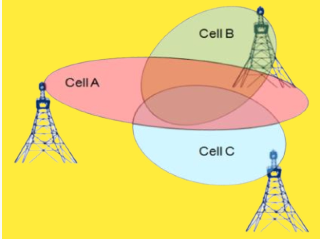
Some cell that greatly exceed the average height of the surrounding buildings can transmit signals far away along the hill terrain or roads. This form a dominant coverage in the other base stations’ coverage, resulting the phenomenon of “island effect”. When a call is connected to this “island” area, the call drop will occur once the mobile station leaves the “island” coverage. As the cells surrounding the “island” are not set as the neighboring cell. Even if neighboring cells are configured, call drops may occur because the area of the island is too small.
On the two sides of the harbor/bay, if the planning of the base station is not designed properly, the cross coverage of these two base stations will happen. As a result, interference may occur.
Common Cause Analysis
o Antenna feeder factor: The height of the antenna (or MU) is too high, the azimuth or downtilt is improperly set, or the transmit power of the base station is too large.
o Site factor: Because of the “waveguide effect”, the signal travels very far along the street.
o Radio environment factors: Reflection from large areas of water etc.
Impact on the Network
o Service: Overshoot coverage may cause ping-pong handovers or interference, poor service experience, and call drops.
o Network KPI: High call drop rate, low handover success rate, and low rate.
The main causes of overshoot coverage are as follows:
The site height is too high.
The antenna downtilt is improperly set.
The transmit power of the base station is too high.
Propagation environment is some special scenarios, such as: cells along the road direction, it is very easy to generate street waveguide effect, and the signal may cover a long distance along the road.
On the two sides of the river or bay, the radio propagation environment is good and signals are difficult to control. Therefore, the overshoot coverage problem can easily occur.
Solution for Overshoot Coverage Problem
- If the site is too high, reduce the antenna height.
- Adjust the antenna azimuth to prevent the antenna’s main lobe direction from spreading to the road, so that the main lobe direction is slightly inclined to the road direction.
- If the antenna azimuth is reasonable, adjust the downtilt. The downtilt can be adjusted based on the electrical downtilt and mechanical downtilt. The electrical downtilt is preferentially used then the mechanical downtilt.
- Reduce the cell transmit power without affecting the cell service performance.
- If the preceding measures do not work:
- Configure neighboring relations based on the actual test result to ensure that the handover is normal and the service is continuous.
For a high site, a more effective method is to replace the site or adjust the transmit power of the base station, or adjust the downtilt of the antenna to reduce the coverage of the base station.
When the coverage cannot be effectively improved, adjust the cell parameters to minimize the interference impact.
Avoid the antenna face directly on the road or use the blocking effect of surrounding
buildings to reduce the overshoot coverage. In addition, check whether co-channel interference occurs on other base station.
The difference between overshoot coverage and weak coverage is not absolute. If the signal quality of the dominant cell in an area is poor, while its overshoot coverage in the far area is dominant, this scenario can be considered as overshoot coverage or weak coverage or both.
The specific solution can be used to enhance the cell coverage in the cell area, or weaken the coverage of the overshoot area.
How to adjust accurately and minimize the impact to other cell are highly depends on the actual situation and the experience of the optimization engineers.
Overlapping Coverage.
The overlapping coverage problem mainly referred to the deep overlapping of multiple cells where the RSRP is strong, but the SINR is poor. Or ping-pong handovers between multiple cells cause poor user experience.
The following two conditions can be used to determine whether overlapping coverage problems exist:
o Absolute RSRP threshold: RSRP in the overlapping area > threshold of more than or equal to 3 cells.
o Relative RSRP threshold: The number of cells whose RSRP difference with the strongest cell is within a certain threshold (3 dB) is more than or equal to 3.
Overlapping coverage is mainly caused by densely distributed sites in urban areas and strong signal coverage. The azimuth and downtilt of each antenna are improperly set, resulting the overlapping coverage of multiple cells.
There is no clear specification on RSRP threshold for overlapping coverage. Operators can define the RSRP threshold based on the site requirements.
Impact on the Network
o Service: Introduce interference among intra-frequency cells and cause poor service quality; Frequent handovers may cause call drop.
o Network KPI call success rate is low, call drop rate is high, number of handovers is high, and handover success rate is low.
Overlapping coverage areas:
o Crossroads, viaduct, highways, high-rise buildings in dense urban areas and water area and surrounding areas.
In the ideal conditions, the signal of each cell should be strictly controlled within its design range. However, due to the complexity of the radio environment: The influence of the terrain, building distribution, street distribution, water and so on, makes the signal very difficult to control and cannot meet the ideal condition.
Overlapping coverage is mainly caused by multiple base stations. Therefore, overlapping coverage mainly occurs in urban environments with dense base stations.
In normal cases, the typical areas of the overlapping coverage are: Tall buildings, wide streets, viaduct, crossroads, areas around the reservoir.
Solutions to Overlapping Coverage Problems.
- The overlapping coverage problem is mainly to solve the signal strength level of each cell in the handover area.
- The common optimization methods are as follows:
- Identify the dominate cell from multiple cells of the problem area.
- Increase the coverage of the dominate cell by adjusting the beam, downtilt, azimuth, and power.
- With similar method, decrease the coverage of the non-dominate cells, decrease the interference.
Overlapping Coverage Optimization Case.
Background: In the Operator XX 5G pilot test, 10 NR sites are build in a ring scenario. During the drive test, dominant cell alternate frequently in a corner, and ping-pong handovers occur between two cells, which affects the test speed in the area.

Cause analysis:
According to the test data, the difference of SS-RSRP level of three cells (PCI=431/435/ 438) at the corner is within 3 dB, and there are three intra-frequency handovers. In the NSA networking, the frequent handovers cause the speed drop in the test.
Checked the A3 event configuration on the SgNB. The sum of the A3 hysteresis (Hys) and offset (Off) is 1 dB. In the overlapping coverage area, this threshold is too low, causing frequent UE handovers.
A3 formula Mn+Ofn+Ocn-Hys > Ms+Ofs+Ocs+Off
Processing result:
o Increase the downtilt angle of the 431 cell to 3 degrees and the downtilt angle of the 438 cell to 2 degrees.
Adjust the HandoverA3Hyst of the 435 cell to 4 to increase the difficulty of intra-frequency handovers.
After the preceding two steps are performed, the number of handover is decreased to 1 and the speed test is improved.