RF module data configuration involves setting parameters such as carrier frequency bands, RAT type, the number of carriers, and channel configuration. The process is constrained by hardware capabilities and software limits. These restrictions ensure compatibility and optimal performance of RF modules in multi-RAT scenarios. Proper configuration is essential to meet technical requirements and maintain efficient operations.
How to Configure Carrier and Power in RF Module?
Carrier frequency band:
Carrier frequency band configuration ensures that carrier signals fit within the RF module’s supported frequency range. For instance, the RRU5258 supports 2300–2400 MHz. The carrier’s lowest frequency must exceed 2300 MHz, its highest frequency must be below 2400 MHz, and the occupied bandwidth (OBW) cannot exceed 100 MHz. These constraints ensure proper functionality and spectrum compliance.
Carrier RAT:
Carrier RAT configuration varies based on the RF module and frequency band. For example:
- The RRU5502 (1800 MHz + 2100 MHz) supports GSM, LTE FDD, NB-IoT, and NR FDD at 1800 MHz, and UMTS, LTE FDD, and NR FDD at 2100 MHz.
- The RRU5258 (2300 MHz) supports LTE TDD and NR TDD.
Number of carriers:
The number of carriers an RF module supports depends on its hardware and software capabilities. For multi-RAT configurations, the maximum carriers for any single RAT are equal to or less than the total carriers the RF module supports when working in a single RAT. This ensures the efficient allocation of resources while maintaining compatibility across multiple RATs.
Carrier bandwidth:
Carrier bandwidth support varies between modules, even for the same RAT. For example, the RRU5904 (2100 MHz) supports a maximum carrier bandwidth of 40 MHz in NR FDD, while the RRU5258 (2300 MHz) supports up to 100 MHz in NR TDD. This reflects the differing capabilities and design optimizations of each module to accommodate specific deployment scenarios and frequency bands.
Channel configuration:
Single-channel RAT: A single channel on an RF module cannot support three or more carriers simultaneously in certain configurations, such as GUL/GUN (FDD) or GULN (FDD) carriers on the same frequency band. Hardware limitations also restrict carrier assignments on specific channels. For example, the RRU5862 (1800 MHz+2100 MHz) supports GSM carriers only on certain channel groups, such as PA1–PA4 or PA5–PA8. For detailed configurations and power settings, refer to the product documentation of the specific base station model.
The total single-channel power of RF carriers must not exceed the maximum allowable output power. Power spectral density (PSD) is calculated by dividing the carrier’s output power by its bandwidth (using 5 MHz for narrow bandwidths like 1.4 MHz or 3 MHz). High PSD can lead to clipping and intermodulation, degrading RF performance. For multi-RAT carriers on one channel, it is recommended to maintain equal PSD values across carriers to ensure compliance with RF specifications and avoid performance issues.
Minimum single-channel NR power: To ensure proper NR cell performance, the minimum single-channel NR output power must be at least the total rated power per PA of the RF module divided by 16. For example, if an RRU has a maximum output power of 2 × 80 W, the minimum configurable NR cell power is 5 W (80 W ÷ 16). This requirement guarantees sufficient signal quality and coverage for NR operation.
Minimum single-channel NB-IoT power: The minimum single-channel NB-IoT power depends on its operational mode:
- Guard band/in-band mode: Minimum power equals the total rated single-channel power divided by 10,000.
- Standalone mode: Minimum power equals the total rated single-channel power divided by 100.
For example, with a maximum RRU output of 2 × 60 W, the minimum NB-IoT power is 0.006 W (60 W ÷ 10,000) in guard band/in-band mode and 0.6 W (60 W ÷ 100) in standalone mode. This ensures appropriate signal levels for various NB-IoT modes.
Single-Band RF Module Configuration.
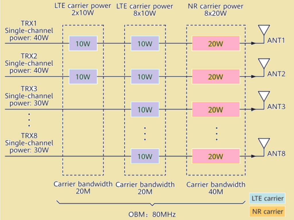
The RRU5258 (2300 MHz) is a single-band RF module designed for efficient LTE and NR deployments, with a maximum transmission mode of 8T8R, output power of 8 × 40 W, and a maximum occupied bandwidth (OBW) of 100 MHz. Engineers can configure it to optimize performance across multiple carriers. For example, one 2T LTE carrier can operate at 10 W output power with a bandwidth of 20 MHz, while an 8T LTE carrier uses similar power and bandwidth. Additionally, an 8T NR carrier supports 20 W output power with a 40 MHz bandwidth, ensuring efficient spectrum usage.
Below table shows the module-level carrier and power configurations of RRU5258 (2300 MHz).
| Model | RAT | Total Number of LTE Carriers | Output Power per LTE Carrier (W) | LTE Bandwidth (MHz) | Total Number of NR Carriers | Output Power per NR Carrier (W) | NR Bandwidth (MHz) |
|---|---|---|---|---|---|---|---|
| RRU5258 (2300 MHz) | TN TDD | 1 (MIMO, 2T) +1 (MIMO, 8T) | 2 x 10 +8 x 10 | 20 | 1 (MIMO, 8T) | 8 x 20 | 40 |
The RRU5258 (2300 MHz) has eight TX/RX channels that can be flexibly configured based on deployment requirements. In a typical power allocation scenario, 2T LTE carriers may utilize channels 1 and 2, while 8T LTE and NR carriers operate across all eight channels. Each configuration adjusts single-channel power and bandwidth to meet specific requirements while staying within the RRU’s capacity limits.
| Model | Channels 1 to 2 | Channels 3 to 8 | ||||||
|---|---|---|---|---|---|---|---|---|
| RRU5258 (2300 MHz) | Number of LTE Carriers | Output Power per LTE Carrier (W) | Number of NR Carriers | Output Power per NR Carrier (W) | Number of LTE Carriers | Output Power per LTE Carrier (W) | Number of NR Carriers | Output Power per NR Carrier (W) |
| 2 | 10 | 1 | 20 | 1 | 10 | 1 | 20 | |
From the perspective of the RF module, the power configurations ensure optimal utilization of resources while adhering to hardware limitations. Channels 1 and 2 are configured with two 10 W LTE carriers and one 20 W NR carrier, reaching the maximum single-channel output power of 40 W. Channels 3 to 8 are configured with one 10 W LTE carrier and one 20 W NR carrier, totaling 30 W per channel. The overall occupied bandwidth (OBW) is 80 MHz, well within the module’s 100 MHz capability, enabling efficient multi-RAT deployment.

Multi-Band RF Module Configuration.
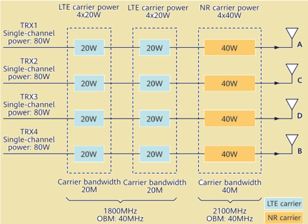
The RRU5502, a dual-band module supporting 4T4R, can deliver up to 4 × 80 W in single-band or dual-band operation. In the proposed configuration:
- For the 1800 MHz band, one LTE carrier and one NR carrier are configured, each with 20 W output power and 20 MHz bandwidth.
- For the 2100 MHz band, one NR carrier is configured with 40 W output power and a 40 MHz bandwidth.
This setup maximizes the module’s capacity while meeting the requirements of LTE and NR carrier configurations.
Below table shows RRU5502 (1800 MHz+2100 MHz) module-level carrier and power configurations.

The mapped configuration for the RRU5502 illustrates shared TX and RX channels for the 1800 MHz and 2100 MHz bands. Each channel is configured with one 20 W LTE carrier and one 20 W NR carrier on 1800 MHz, and one 40 W NR carrier on 2100 MHz. This setup achieves a total output power of 80 W across all channels. The occupied bandwidth (OBW) of 40 MHz for both bands adheres to the module’s bandwidth specifications, ensuring efficient use of its capabilities.

Tri-band module.
The RRU5519et is a tri-band module supporting 700 MHz, 800 MHz, and 900 MHz frequency bands with a maximum TX/RX mode of 2T4R. It allows a total output power of 2 x 160 W across all bands, but with restrictions. The output power for any single frequency band on a single channel cannot exceed 80 W. Additionally, the combined output power of the 700 MHz and 800 MHz bands on a single channel must not exceed 80 W, and the total output power of all bands on a single channel must not exceed 160 W.
The RRU5519et operates under specific power constraints. When working exclusively on the 700 MHz or 800 MHz bands, the maximum output power of a single channel is 80 W. If both bands are used simultaneously, their combined power also cannot exceed 80 W. The module’s four TX/RX channels are distributed such that two channels are shared by the 700 MHz and 800 MHz bands, while the other two are reserved for the 900 MHz band. For all three bands, the module supports a maximum total output power of 160 W.
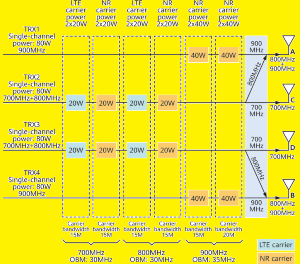
In the proposed configuration for the RRU5519et module:
- 700 MHz + 800 MHz: Each band is configured with one LTE and one NR carrier, with each carrier transmitting at 20 W. The carrier bandwidth for both bands is set to 15 MHz.
- 900 MHz: Two NR carriers are configured. Each carrier transmits at 40 W, with bandwidths of 15 MHz and 20 MHz, respectively.
This setup aligns with the module’s power and bandwidth constraints, ensuring efficient use of shared and independent TX channels.
Table below shows Module-level carrier and power configurations for the RRU5519et (700 MHz+800 MHz+900 MHz).

The RRU5519et module allocates its TX channels based on frequency bands to optimize RF performance and mitigate passive intermodulation (PIM3) effects. The 700 MHz and 800 MHz bands share one TX channel, while the 900 MHz band uses independent TX channels. Antenna port mapping is as follows: 700 MHz is mapped to ports C and D, while 800 MHz and 900 MHz are mapped to ports A and B. This flexible mapping ensures effective RF performance and meets design constraints.

Read Also: