The RAN enables network slice deployment by aligning with core network configurations for end-to-end interconnection. It ensures SLA compliance and user experience through effective radio resource management and admission control tailored to the needs of each network slice, supporting diverse service requirements like eMBB, URLLC, and mMTC.
RAN Network Slicing Implementation
During deployment, network slices are associated with tracking areas and NG interfaces to ensure the RAN is aware of the slices configured on the core network.

The gNodeB maps network slices to cells via tracking areas and routes data to the AMF or UPF through the NG interface. VLAN IDs are used to isolate network slice data within the transport network, ensuring separate transmission channels and maintaining service isolation and SLA compliance across slices.

During network slice deployment, a default AMF and UPF are essential to handle UEs without explicit slice identifiers (S-NSSAI or Temp ID). The default AMF manages such UEs by ensuring access to the network, while the default UPF guarantees proper service availability for these UEs. This setup ensures seamless operation and fallback mechanisms, supporting a robust network slicing infrastructure.
The gNodeB selects a default AMF in some scenarios. How is an AMF selected in other scenarios?
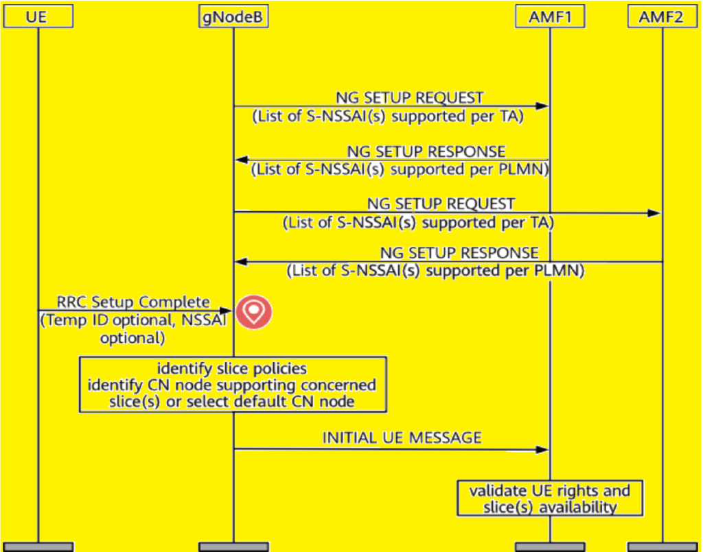
The selection of an AMF for a network slice UE depends on the presence of S-NSSAI or Temp ID in the UE’s Msg5 during the initial network access. If the S-NSSAI is reported, the gNodeB uses it to determine the appropriate AMF. If only a Temp ID is provided, the gNodeB retrieves the associated slice information for AMF selection. In cases where neither is provided, the default AMF is used, ensuring the UE can still connect and access services reliably.
AMF selection:
| Temp ID | S-NSSAI Supported by the gNodeB | AMF Selection |
|---|---|---|
| Not present or invalid. | Present. | The gNodeB selects the AMF corresponding to the NG interface associated with the network slice. |
| Present and valid. | Present or not present. | The gNodeB selects the AMF associated with the Temp ID. |
| Not present or invalid. | Not present or invalid. | The gNodeB selects a default AMF associated with an NG interface configured on the network. |
How is the RAN made aware of the network slices configured on the core network side after network slices are deployed on the RAN side?

In the network slicing process, the UE sends an NAS message with S-NSSAI information to the gNodeB, which forwards it to the core network. The core network checks if it supports the requested slices. If supported, it requests a PDU session via a PDU SESSION RESOURCE SETUP REQUEST. The gNodeB verifies if it can support the slice, then responds with either a success or failure message, indicating the status of the PDU session establishment based on slice compatibility.
Network Slice Resource Management
RAN resources for network slices consist of the number of UEs connected in an NR cell and the RBs in an NR DU cell. Each NR cell is set up on a gNB-CU, while NR DU cells are managed on a gNB-DU. Network slicing within the RAN is organized at the granularity of a network slice group, which can contain multiple network slices, each associated with a specific group and assigned to only one group.
Why are RAN resources for network slices managed at the granularity of a network slice group instead of a network slice?
RAN resources are managed at the granularity of a network slice group rather than a single network slice to optimize resource allocation. In cases with many slices, multiple slices can be grouped, enabling more flexible and efficient resource management. For scenarios with fewer slices, grouping can still achieve the same effect as managing resources at the slice level. This approach ensures scalability and efficiency, particularly when managing resources across a wide range of network slice configurations.
RRC_CONNECTED UE Number Management
The number of RRC_CONNECTED UEs in an NR cell is managed by configuring the maximum number of UEs for each network slice group. The network slice group ID is associated with an NR cell and its resources, which are also linked to individual network slices. This configuration ensures that UEs are distributed efficiently across different network slice groups within the NR cell, optimizing resource allocation for the network.

RB Management
RB management in 5G is categorized into three resource allocation methods:
- QoS-based scheduling: Allocates resources based on service quality requirements.
- RB reservation: Reserved resources for network slice groups.
- Carrier isolation: Exclusively assigns carriers to specific slices in non-co-cell scenarios.
QoS-based scheduling and RB reservation apply in co-cell scenarios, while carrier isolation is used when dedicated carriers are assigned in non-co-cell configurations. Each method ensures efficient management and prioritization of resources in the network.
QoS-based scheduling
In QoS-based scheduling, network slices share RBs within the cell, and their access to resources is prioritized according to QoS requirements. Each network slice is defined at the PDU session level, with one PDU session belonging to one network slice, though multiple PDU sessions can belong to a slice. The gNodeB processes the network slice and QoS information for each radio bearer, enabling differentiated treatment based on the QoS flow of the PDU session.

In QoS-based scheduling, two scenarios arise:
- A network slice with only one type of QoS flow, where scheduling priorities align with the QoS priorities.
- A network slice with multiple QoS flows, where different flows are distinguished by 5QI values. In this case, prioritization is based on 5QIs rather than network slices, essentially resembling a non-sliced scenario.
In QoS-based network slice scheduling, different network slices can share the same RBs in an NR DU cell, with distinct QoS levels (e.g., 5QI 9 for eMBB and 5QI 69 for URLLC) to meet specific SLA requirements. However, QoS-based scheduling does not allocate resources at the granularity of a network slice group. It operates within the framework of the 5G SA QoS architecture and control mechanisms, ensuring that resource allocation is based on QoS priorities.

RB reservation
RB configuration:
In RB configuration, NR DU cell resources are associated with NR DU cell IDs and resource IDs, indicating the resources available to a network slice group. A network slice group ID is associated with the NR DU cell and its resources. Network slices are then configured and added to network slice groups to allocate RBs efficiently. This setup ensures that the RBs are used by UEs corresponding to a specific network slice group.

The percentages in RB configuration define the allocation and usage of NR DU cell resources for UEs in a network slice group:
Maximum Percentage of RBs: The highest RB quota allowed for UEs in the slice group, not reserved for preferential use.
Minimum Percentage of RBs: Dedicated RB quota exclusively for UEs in the slice group, with a configurable frequency start position.
Percentage of Prioritized RBs: RB quota preferentially used by UEs in the slice group but shared when unused.
The RB resources for UEs in a network slice group are allocated hierarchically: the minimum percentage of RBs is guaranteed as dedicated resources, followed by the percentage of prioritized RBs, which are preferentially used but shared if idle, and lastly, the maximum percentage of RBs defines the total ceiling of resources available for the group. This ensures an orderly and prioritized distribution while maintaining flexibility in resource utilization.

Each NR DU cell supports up to six network slice groups, ensuring each group consists of network slices from the same operator. In multi-operator scenarios with shared NR DU cells, operators can configure one or more groups, provided the total does not exceed six. RB reservation is primarily for URLLC slices, ensuring guaranteed and dedicated resources to meet ultra-reliable and low-latency communication needs, as shown in Figure. This approach helps maintain SLA requirements for URLLC services while optimizing resource allocation.

RB resource control policy.
The RB resource control policy includes TTI-based and mean-type methods:
- TTI-based control policy: RB scheduling is performed for a network slice group during every TTI, allowing precise and immediate resource control.
- Mean-type control policy: RB scheduling is based on the average PRB usage of UEs in the network slice group, without requiring control during every TTI. This approach focuses on long-term resource usage efficiency.
Each method tailors RB scheduling mechanisms to optimize network performance and meet service requirements.

When the TTI-based control policy is applied, resource scheduling is performed in each TTI by adhering to the configured resource percentages for the network slice group. The scheduling considers the following:
- Minimum percentage of RBs.
- Percentage of prioritized RBs.
- Maximum percentage of RBs.

When the mean-type control policy is applied, scheduling ensures that the average PRB usage over a defined period aligns with the configured minimum, prioritized, or maximum percentage of RBs for a network slice group.
Carrier isolation
Carrier isolation allocates a dedicated carrier for each network slice, ensuring that the resources of one slice are entirely separate from those of another. In this method, network slices operate exclusively on their assigned carrier, using only the RBs within the local cell. This approach guarantees complete isolation between slices, offering robust separation for services with distinct requirements. For example, eMBB slice UEs and URLLC slice UEs are served on different carriers, isolating their respective RB resources for SLA assurance.

Network Slice Admission Control
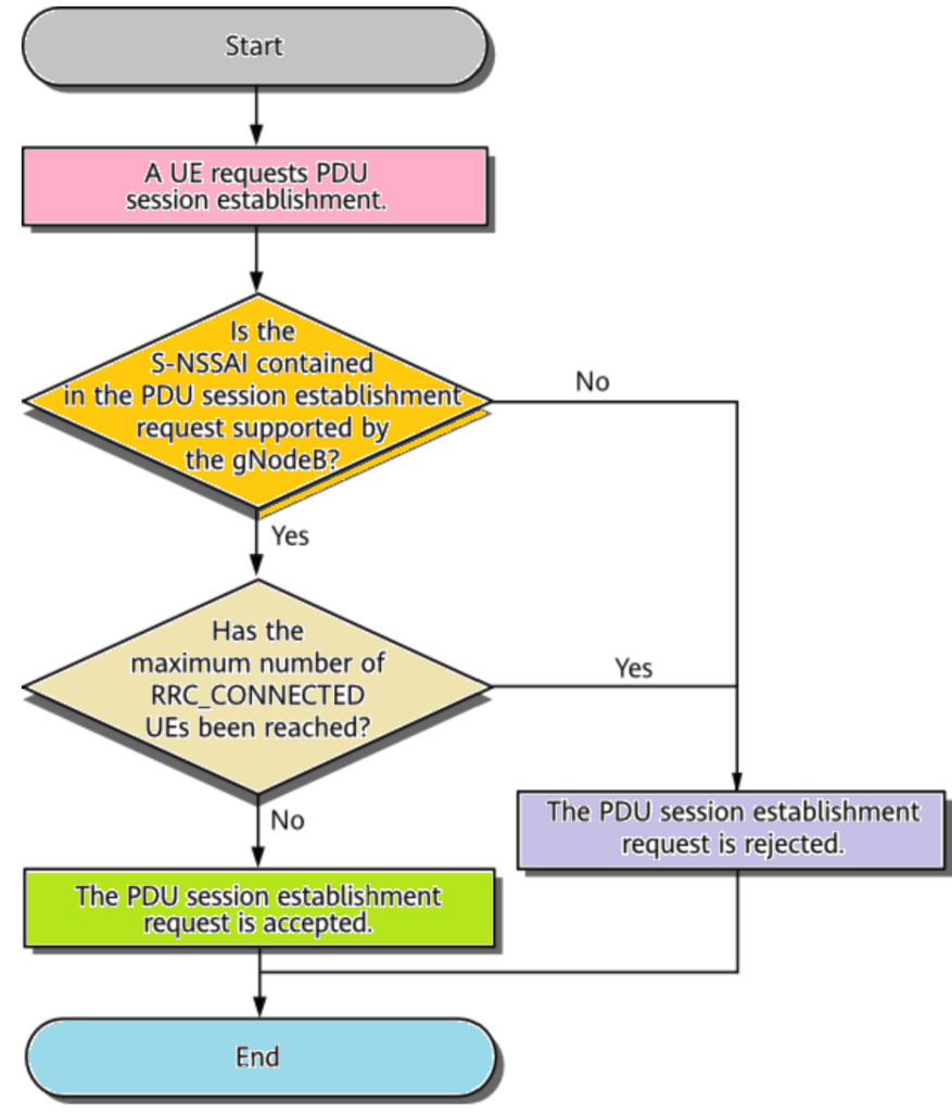
After deploying network slices on the RAN side, whether UEs can access the network-slice-specific cell depends on the isolation level between slices. Admission control ensures access is managed by evaluating the support for a particular network slice and the maximum allowable RRC_CONNECTED UEs. The number of UEs permitted in an RRC_CONNECTED state for each slice can be configured to maintain resource allocation and service quality. For more details, refer to mechanisms like RRC_CONNECTED User Number Management.
During PDU session establishment or RRC connection resume/reestablishment, the gNodeB validates the S-NSSAI in the request against its configured S-NSSAIs. If a match is found and the maximum number of allowed RRC_CONNECTED UEs has not been exceeded, the PDU session can proceed for the UE. This ensures proper resource management and adherence to network slice configurations.
During handovers, the gNodeB performs admission control by verifying whether the UE’s network slices align with the network slices supported by the target cell (matching S-NSSAI). If they overlap and the maximum number of RRC_CONNECTED UEs in the target cell has not been reached, the handover is considered successful. This ensures network slice compatibility and resource availability in the target cell.
The admission mechanism varies in the following handover scenarios:
Intra-base-station and Xn-based handovers:
The source cell determines whether a UE’s network slices overlap with those supported by the target cell using the target’s slice configuration. If there is overlap, the UE sends a handover request, and the target cell performs admission control based on slice support. If all UE slices are supported by the target cell, the handover is successfully executed. This process ensures seamless slice-aware handovers while maintaining network efficiency.
If a UE’s network slices are only partially supported by a target cell and a handover is deemed necessary (such as for coverage-based intra-frequency or inter-frequency reasons), the handover is performed. However, services linked to unsupported slices are released. If the handover is unnecessary (not coverage-based), it is not executed. This ensures efficient resource utilization and service continuity while maintaining the integrity of network slice support.
NG-based handover:
In NG-based handover scenarios, the source cell lacks information about the target cell’s network slice configurations. Therefore, the UE initiates the handover, and the target cell performs admission control.
- All Slices Supported: Handover proceeds successfully.
- Partial Slice Support:
- If necessary (e.g., for coverage), the handover is executed, and unsupported slices are released.
- If unnecessary, the handover is initiated but results in a preparation failure notification.
- No Slices Supported: Handover preparation fails, and the procedure stops.
In NG-based handovers, a penalty mechanism is used when the target cell does not support a network slice available in the source cell. If the slice is unsupported, handovers to the target cell for UEs using that slice are restricted for a specific period. This restriction is governed by the slice-not-supported timer, ensuring targeted handover management and avoiding unnecessary attempts to incompatible cells. This mechanism enhances efficiency in managing slice-based resources across network cells.
In scenarios where the maximum number of RRC_CONNECTED UEs in a target cell is reached, a penalty is applied. If a UE fails to handover due to this limitation, the target cell will reject further handovers from the source cell for any UEs with the same network slice for a defined period. This penalty is enforced after the slice-resource-unavailable timer is set, ensuring that handovers are prevented for that specific slice until resources become available again.
References
- 3GPP TS 23.203, Policy and charging control architecture.
- 3GPP TS 23.501, System architecture for the 5G System (5GS); Stage 2.
- 3GPP TS 38.300, NR; NR and NG-RAN Overall Description; Stage 2.
- 3GPP TS 38.413, NG-RAN; NG Application Protocol (NGAP).