The main points and Keywords to be discussed in this article are testing and commissioning of ac ups system. ups system electricala. Inverter. Static transfer switch overload test. Inverter overload test.
TOOLS AND EQUIPMENT TESTING AND COMMISSIONING OF ELECTRICAL EQUIPMENT
Tools and equipment should be in good condition for use in the construction area. All test equipment required to be calibrated not more than 3 months before the date of test. All equipment calibration “original” certificates should be presented at site.
These includes but not limited to the following:
- Common Hand Tools
- Digital Volt-ohm Meter
- 500/5000V MEGGER
- Current Tester (Multi-Amp or equal)
- Torque Wrench
- Ductor (Micro ohm Meter)
- Protective Relay Test Set
- Thermometer
- Oscilloscope
- Load Bank
- Manufacturer’s Instruction Manuals
- Personal Protective Equipments
- Timing Tester
- Hydrometer
- Relay testing set
- DLRO
PROCEDURES FOR TESTING AND COMMISSIONING OF AC UPS SYSTEM
GENERAL PREPARATORY WORKS
- COMPANY shall appoint qualified employees as their ‘competent persons’. Such persons shall be capable of working safely and shall be knowledgeable on the precautionary techniques, personnel protective equipment, shielding and insulating materials and tools.
- All permanent and consumable materials shall prepare prior to testing.
- Manpower, equipment, tools and other logistics shall be prepared and ready for installation.
- Prepare the workplace such as barricading the area and housekeeping.
- Review the AC/DC control schematic of the disconnect switch assembly. All connection diagram vendor and IFC drawing shall be available in the work area.
- Review all technical specifications, operating manuals and previous inspection data if appropriate.
- Electrically Hazardous Task Plan / Permit shall be completed and signed before any work proceeds.
AC UPS SYSTEM ELCTRICAL COMMISSIONING
Visual Inspection
- Compare equipment nameplate information data with actual operating conditions, drawings and specifications.
- Inspect the physical condition of all electrical and mechanical components for deterioration and missing, broken, or loose parts, etc. This includes the inspection of insulators, insulation materials, sign of overheating or electric sparks and door fastener functionality.
- Check for proper wiring and terminal connection are done.
- Check that all grounding is securely connected (including star neutral points).
- Check cleanliness of interior of cubicle, clean using manufactures approved method and material.
The main points and Keywords to be discussed in this article are testing and commissioning of ac ups system. ups system electricala. Inverter. Static transfer switch overload test. Inverter overload test.
Electrical Commissioning Test
- Performed light load and functional test to verify the UPS is correctly connected and that all functions operate properly.
- Performed No load test. The UPS output voltage shall remain within the specified values when the UPS operates at nominal input voltage, frequency and with no load connected at the output.
- Performed Full load test. The UPS shall remain in normal mode of operation and its output voltage within the specified values when operating at nominal input voltage and frequency, while supplying a reference test load.
- Performed AC input failure test. The test shall be performed with a battery or other appropriate DC source. The input failure should be conducted by interrupting the AC input. Compliance is verified when, following the input AC failure, the UPS operates in stored energy mode within steady state output voltage and frequency limits.
- Performed AC input return. This test shall be performed either by restoring the AC input power, or simulated by energizing all UPS input feeders at the same time. This test shall normally be performed with a battery or appropriate DC source. Proper operation of all UPS rectifiers, including walk-in (if applicable), shall be observed. AC output voltage and frequency variations shall also be measured. Compliance is verified when, following the input AC return, the UPS operates in normal mode within steady state output voltage and frequency limits.
- Rectifier input current walk-in ramp – A resistive load shall be applied in the rectifier output, the rectifier shall be switched ON and shall be verified that the rectifier AC input current gradually increase up to nominal value in a time greater than 10 seconds.
- Performed transfer test to bypass line. System shall be fed according to the rated voltage and shall have the output connected to a resistive load equal to the rated load. Such test will be carried out by simulating an inverter fault as well as the return of the same (through a maneuver command). Such test consists of two parts, as follows:
- Inverter fault simulation. Inverter will be switched off (or output disconnected) for the fault simulation. The system control logic shall switch the load on the bypass line network without voltage lacks.
- Return from inverter fault simulation. Inverter will be switched on (or connected again) for the return simulation from the inverter breakdown. The system control logic shall switch the load again on the inverter without voltage lacks.
- Performed Inverter stability test in normal mode. Such test shall be carried out on three different load conditions: no load, 25% and 50% rated load, so that almost all possible conditions during the real operation may be simulated. It will deal with pure resistive loads. Such procedure requires the test repetition with the whole rated load (100% In) as referred respectively to the rated supply voltage and to its maximum and minimum values of the allowed range of variation of the mains supply voltage. Test finishes by reading both the output alternate current and voltage having an overload value of 25% as to the rated load (125% In) and to the rated supply voltage as well.
- Performed Dynamic test of inverter load variation. The system shall be fed according to the mains input rated voltage. Only pure resistive loads will be used, unless otherwise requested by the Customer. Such test consists of two parts, corresponding respectively to the load insertion and disconnection, as follows:
- Load insertion. The system, firstly without load, is suddenly switched on a load equal to 100% of the rated load.
- Load disconnection. The system, firstly connected to a load equal to 100% of the rated load, is suddenly disconnected from the load.
- 3-Phase unbalance test for testing and commissioning of ac ups system. The purpose of this test is to check the output UPS voltage and phase angle deviation with unbalance load conditions.
- Output voltage unbalance on three-phase output UPS shall be checked under symmetrical load conditions and unbalanced load conditions. For the unbalanced load condition, two phases shall be loaded phase to phase or phase to neutral if a neutral exists at nominal rated current linear load, the other phase at no load unless otherwise specified by the manufacturer/supplier.
- Phase-to-phase and phase-to-neutral (if neutral provided) output voltage have to be observed. Voltage unbalance shall be given in terms of voltage unbalance ratio. Phase angle deviations shall be determined by calculation from the values of phase-to-phase and phase-to-neutral voltages.
Performed Inverter overload test
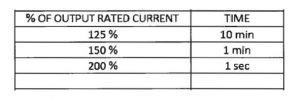
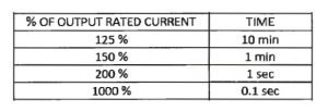
Bypass line shall be disconnected. With the Inverter operating under light load in normal mode, apply a resistive load which shall result in the Inverter output in excess of the manufacturer’s full load rating specified in table A. Check that the Inverter continues to operate within the manufacturer’s stated conditions for the period of time specified in table
The main points and Keywords to be discussed in this article are testing and commissioning of ac ups system. ups system electricala. Inverter. Static transfer switch overload test. Inverter overload test.
Performed Static transfer switch overload test
Inverter shall be switched off. With the UPS operating under light load in normal mode, apply a resistive load which shall result in the UPS output in excess of the manufacturer’s full load rating specified in table B. Check that the UPS continues to operate within the manufacturer’s stated conditions for the period of time specified in table
Performer Rectifier static stability test for testing and commissioning of ac ups system. Such test shall be carried out on three different load conditions: no load, 50% total load and 100% total load and different charging conditions such as float charge and equalize charge, so that almost all possible conditions during the real operation may be simulated. It shall only deal with resistive loads. As far as each condition is concerned, output voltage and current will be measured as respectively referred to the rated supply voltage and its minimum and maximum values of the whole allowed range of variation of the mains supply +/-10% voltage variations
Measurement of the rectifier output ripple voltage. The purpose of this test is to check that the rectifier output voltage ripple is within the stability values allowed, with respect to all the load conditions which may occur during the real operation as well as all supply voltage values within the allowed range of variation of the mains supply voltage.
Burn-in Test, during such test before testing and commissioning of ac ups system, the system shall be connected to the rated mains supply voltage and connected to a pure resistive load equal to 100% of the rated load. Such system will operate according to these conditions for 72 hours. During the whole test, the output current, voltage values and temperature in the most critical points through thermocouples will be read on a regular time basis.
The main points and Keywords to be discussed in this article are testing and commissioning of ac ups system. ups system electricala. Inverter. Static transfer switch overload test. Inverter overload test.

