The purpose of this article is to establish recommended guidelines for the selection of recycle valves for salt water disposal pumps to be installed at industrial and plant facilities. This defines minimum engineering requirements for the analysis and design of control valves for recycle applications for produced water disposal pumps.
Selection of Recycle Valves for Salt Water Disposal Pumps
PROCESS ANALYSIS
The extreme pressure drop across these recycle valves, in relation to the process vapor pressure, makes such application prone to very severe cavitation conditions. A typical value for the process cavitation index is:
In addition to the fact that water cavitation is the worst among incompressible fluids, such high value of process cavitation index limits the valve design very significantly. Any proposed design has to have a cavitation index (Kc) of 0.9704 or more (given water conditions and high DPs).
The presence of considerable amount of dissolved salt (and therefore chlorides) mandates a valve/trim material with high Pitting Resistance Equivalent Number (PREN). The high solid content dictates hard material for the valve/trim to withstand erosion and a non-restrictive geometry to minimize probability of clogging. Furthermore, the high H2S and CO2 content mandates the valve and trim material to be NACE/ISO 15156 compliant. Very few material type/grade qualify for these constrains when coexist.
The continuous duty cycle is a major challenge as well. Although these valves were selected with the assumption that they will be infrequently online, operation tend to operate them more frequently and leave the pump running on bypass to avoid pump shutdown. This complicates valve selection.
FAILED ATTEMPTS
Several designs were tried before to address this application but failed because they lack thorough understanding of the process. Here are few examples:
Symptom
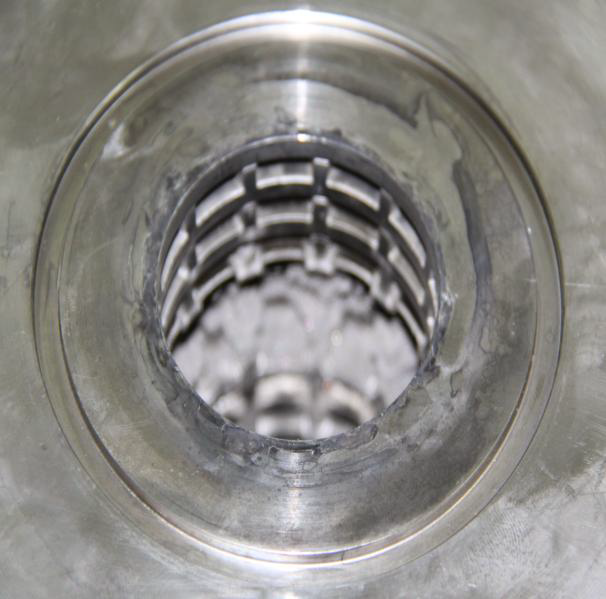
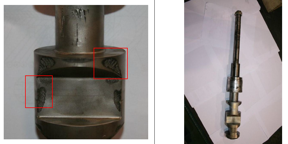
Erosion and pitting on the surface of the plug and cage.
Root Cause
Improper specification of a typical globe valve design (with relatively low Kc value) for this application.
2) Failure 2
Symptom
Erosion and pitting on the surface of the plug, cage and seat ring.
Root Cause
Improper specification of a typical globe valve design (with relatively low Kc value) for this application. Improper use of tortuous cage design which caused frequent clogging.
3) Failure 3
Symptom
Erosion and pitting on the surface of the plug and cage.
Root Cause
Although the right valve type was specified (axial body), the number of pressure reduction stages was not adequate to dissipate the energy associated with DP>3000 psid (Kc<Ksa).
PROPOSED SOLUTION
To propose a solution, each process limitation will first be addressed separately (beginning with the most stringent one to least). Afterward, the proposed solution will be evaluated against all conditions combined.
1. High DP
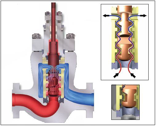
To maintain a Kc value higher than 0.9704 (given water conditions and high DPs), an axial valve body design (Figure 1) is recommended. This body design is available from several Saudi Aramco approved manufacturers (Appendix D).
Depending on the number of pressure reduction stages, the Kc value for this design can reach 0.99 if used with water at DP=4000 psid. This makes it, by far, the best cavitation resistance valve design. The high Kc value, for this design, is attributed to high turbulent mixing at each stage which increases flow friction. The friction is caused by the liquid gliding against the trim surface (at each stage) and the liquid streams gliding against each other because of the high turbulance nature. The high friction loss allows this design to dissipate the required high DP effectively without increasing fluid velocity. Fluid velocity, if not constrained, will drop pressure below the vapor pressure which causes cavitation to occur. Typical values of Kc for this design and other valve designs are shown in Appendix A.

2. Salt
The presence of salt dictates body and trim material that has a high PREN number. The PREN number is calculated from composition of various elements in the steel mixture using the following simplified formula:
where:
Cr: Chromium, Mo: Molybdenum, N: Nitrogen
The best materials used for such applications are super austenitic stainless steels (e.g., S31254 PREN=43 or even better CK3MCuN PREN=45).
Typical PREN numbers are shown in Appendix B.
3. Solids
The presence of solids imposes two challenges:
a) Erosion
Erosion can be addressed and resolved by specifying solid Alloy-6 (CoCr-A) for the trim parts with right angle impingement. Alloy-6 has a superb erosion resistance. For the cage, to avoid galling with the plug, hard duplex SST with ENC coating can be specified.
b) Clogging
Clogging is avoided with the use of the axial body design given its clear flow passages contrary to the tortuous miniature flow cages commonly used for these applications by mistake.
4. H2S & CO2
Since the temperature is low to moderate, S31254 or CK3MCuN, duplex SST and Alloy-6 are NACE/ISO 15156 compliant can be used without any limitations.
Recommendations
In conclusion, it is recommended to specify the recycle valve for salt water disposal pumps with the following attributes:
1. Specify axial body design either globe or angle (depending on piping configuration);
2. Specify the following material for body & trim:
a. Body and bonnet (duplex SST or SMO254)
b. Plug and seat (Solid Alloy-6)
c. Cage (duplex with ENC coating)
d. Stem (duplex or SMO254)
Although the above selection guide will prolong the life of the valve and trim, it will not totally eliminate all associated problems. Frequent maintenance is needed to ensure reliable valve operation. Depending on duty cycle, the above recommended design should be adequate to achieve Mean Time To Failure (MTTF) of 2 to 8 years. Significantly, better MTTFs can be achieved if the differential pressure across the valve is reduced by trimming pump impellers or reducing pump stages. It is recommended that the process design for these pumps be verified to reduce differential pressure requirements to minimum possible extent.
APPENDIX A
Typical Kc Values for Different Valve Design (Courtesy of Emerson Process Management)
APPENDIX B
PREN Number for Typical Metals
APPENDIX C
Chemical Composition for S31254 & CK3MCuN
APPENDIX D
Axial Body Valves from Various Approved Manufacturers


