- SCOPE
- REFERENCE
- DEFINITIONS
- GENERA
- LOCATION SIGNIFICANCE OF ARROW
Welding Symbols Figures
- Standard Location of Welding Symbols
- Basic Weld Symbols (Ideographs)
- Supplementary Weld Symbols
- Design of Standard Symbols (Millimeters)
- Butt Joint
- Corner Joint
- T Joint
- Lap Joint
- Edge Joint
- Typical Welding Symbols
Welding Symbols
1. Scope
This article provides a system for symbolic representation of welds on engineering drawings to facilitate communications among designing, shop, fabrication and inspection personnel.
2. Welding Symbols Reference
Reference is made in this standard to the American Welding Society (AWS). The latest issues, amendments, and supplements to these documents shall apply unless otherwise noted. A2.4 Standard Symbols for Welding, Brazing, and Nondestructive examination.
3. Welding Symbols Definitions
Arrow.
Indicates the joint location on drawing or sketch.
Basic Weld Symbol.
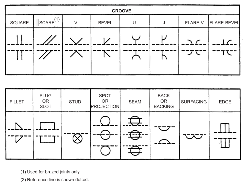
Specifies the type of weld or groove, see Figures 2 and 10.
Finish Symbol.
If the finish specification is to be amplified, a supplementary note is required.
Reference Line.
Provides a means of distinguishing the side of the joint.
Tail.
Used to indicate a specification, welding procedure, process, or other references.
Weld Symbol.
It is the ideograph or picture symbol used to indicate the desired type of weld. See Figure 2.
Welding Symbol
For the welded assembly, it consists of a number of elements, several or more of which are used to specify a weld in varying degrees of completeness. The reference line and arrow are required elements. See Figure 1.
4. Welding General
4.1 The elements of a welding symbol shall have standard locations with respect to each other as shown on Figure 1.
4.2 The basic type of weld (bead, fillet, plug, or slot) and the plate preparation or ‘groove’ into which the weld is to be deposited shall be indicated as shown in Figure 2.
4.3 The weld finish ground or ground flush or convex and supplementary symbols shall be as shown in Figure 3.
4.4 Welding fabricators should have a standard procedure, or method, for preparing the joint and welding.
4.5 The symbols may be used on drawings of welded structures, particularly where a distinction between ‘all-around, intermittent, or plug welds’ would be advantageous.
4.6 Refer to AWS A2.4 for symbols not covered in this standard.
5. Location Significance of Arrow
5.1 The location and elements of the welding symbol as shown in Figure 1are very important. The complete symbol consists of three parts: Part 1, the reference line; Part 2, the arrowhead and line connecting the reference line to the area welded; and Part 3, the weld symbols themselves along the reference line.
5.2 The reference line shall be drawn substantially horizontal as viewed from the position in which the drawing and symbols are to be read.
5.3 The side of the weld joint touched by the arrowhead is known as the ‘arrow side’ and that part of the welding symbol applying thereto shall be written below the reference line. The side of the weld joint away (or opposite) from that touched by the arrow is known as the ‘other side’, and the welding symbol information applying thereto shall be written above the reference line. See Figures 5 to 9.
5.4 When a bevel or J groove weld symbol is used, the arrow shall point (with a definite break or bend) towards the member which is to be beveled, unless otherwise it is obvious.
5.5 The perpendicular leg of the weld symbol shall always be shown on the left. See Figures 6, 7, and 10.
5.6 The arrow shall not be broken when both plates are grooved alike (U or V ).
5.7 In case of plug welds, the arrow shall point to the outer surface of one member of the joint at the centerline of the desired weld. The member to which it points shall be considered as the ‘arrow side’. See Figure 8.
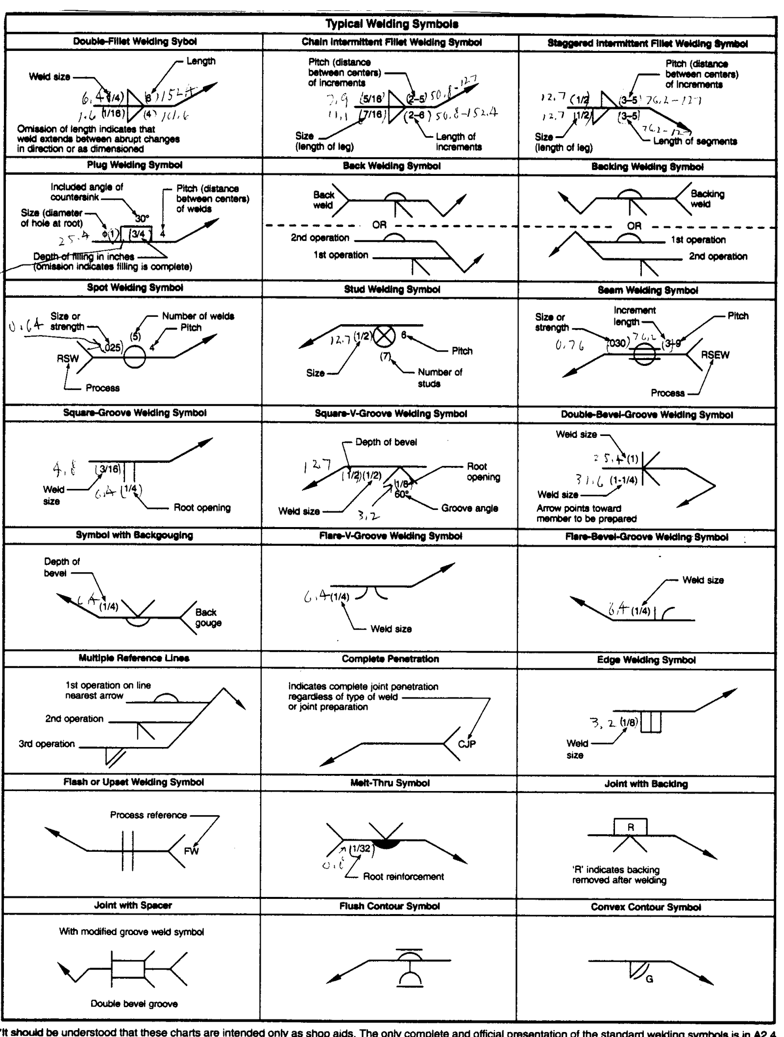
5.8 Figures 4 to 10 illustrate basic and typical welding symbols, design of symbol in millimeters, their location significance, basic type of joints, and the significance of the arrow location.
FIGURE 1 – Standard Location of Welding Symbols
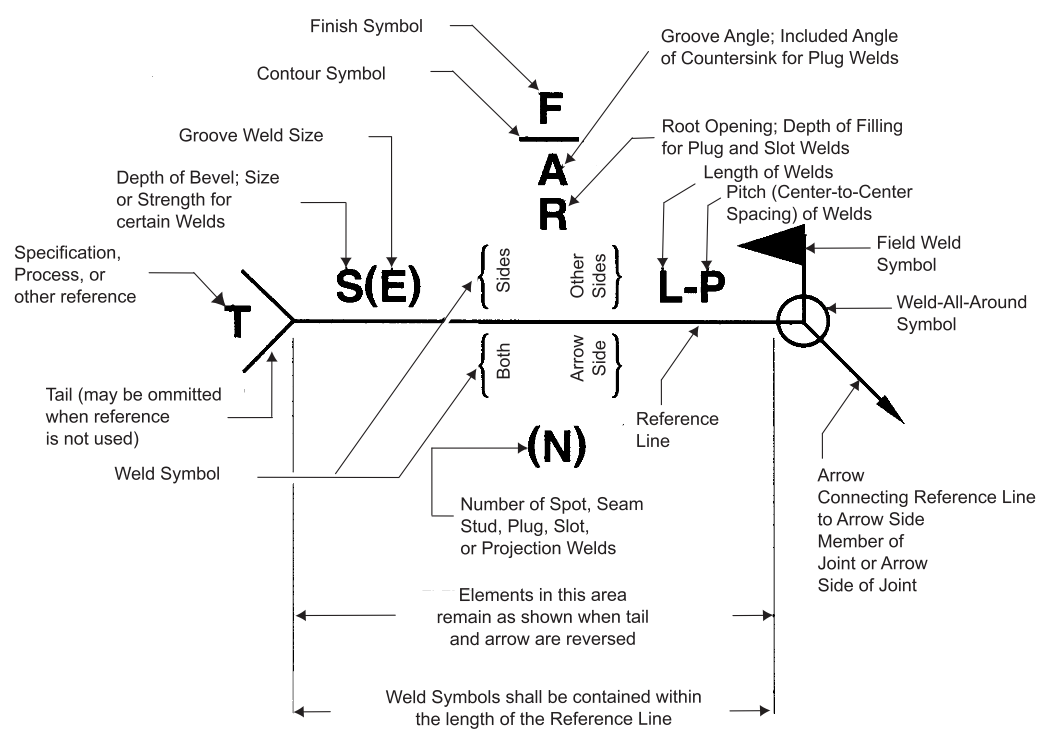
FIGURE 2 – Basic Weld Symbols (2) (Ideographs)
FIGURE 3 – Supplementary Weld Symbols
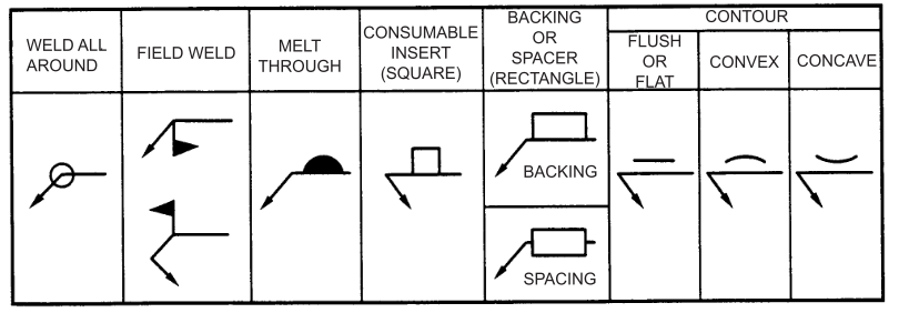
FIGURE 4 – Design of Standard Welding Symbols (Millimeters)
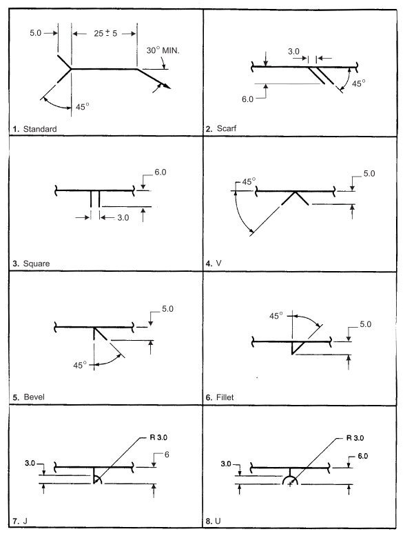
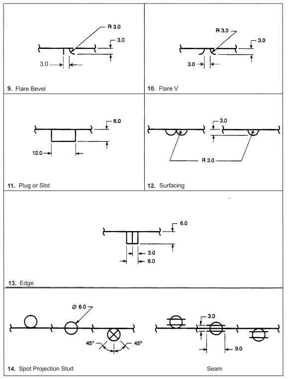
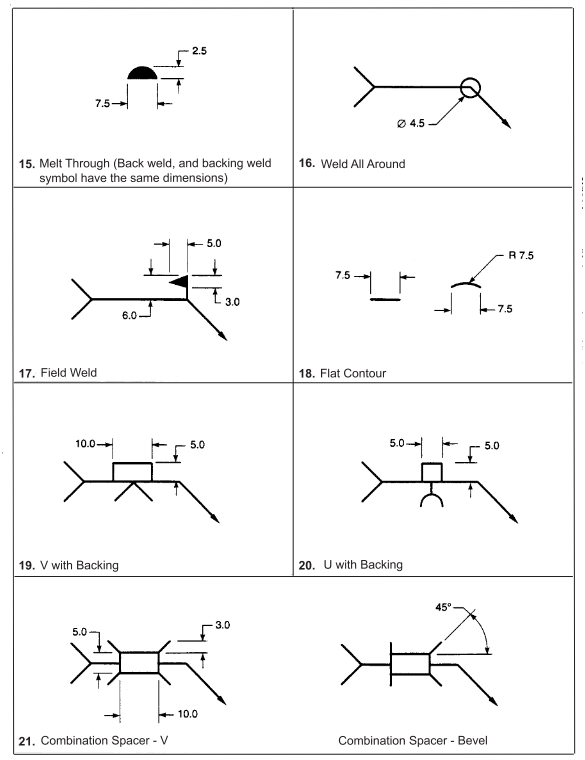
(1) Linear dimensions in millimeters.
(2) Tolerances shall be ± 1 mm or ± 1° as applicable unless otherwise specified.
(3) All radii are minimum dimensions.
FIGURE 5 – Butt Joint (Arrow Side and Other Side Designation of V Groove Weld Symbol)
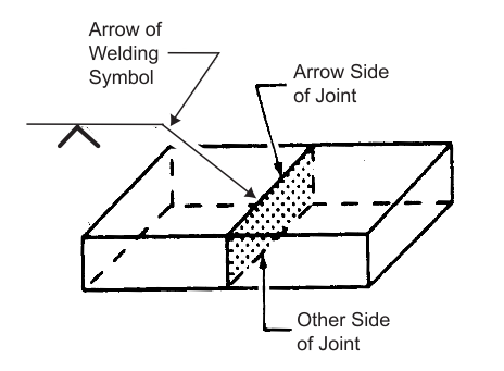
FIGURE 6 – Corner Joint (Arrow Side and Other Side Designation of Fillet Weld Symbol)
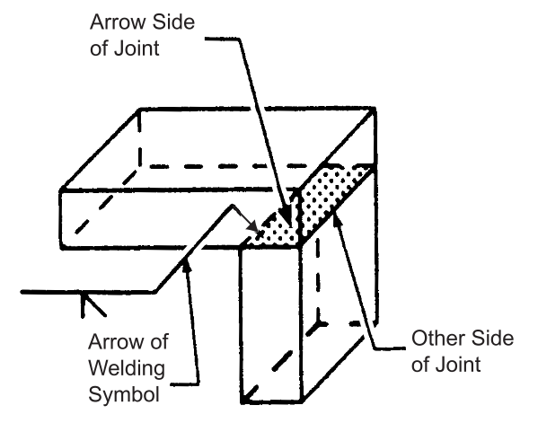
FIGURE 7 – T Joint (Arrow Side and Other Side Designation of Double Fillet Symbol)
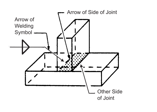
FIGURE 8 – Lap Joint (Arrow Side and Other Side Designation of Plug Weld Symbol
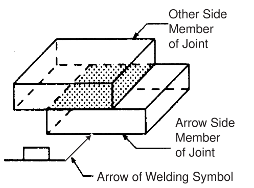
FIGURE 9 – Edge Joint (Arrow Side and Other Side Designation of Edge Weld Symbol
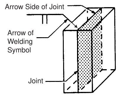
FIGURE 10 – Typical Welding Symbols
