This article is for manufacturing, testing of non-segregated Bus Bars and Bus Ducts rated 600 V to 35 kV as per international standard ANSI C37.23. Main keywords for this article are Bus Bars and Bus Ducts Design Requirements, ANSI C37.23, Bus Bars and Bus Ducts Ratings, Bus Bar Supports, Bus Bars and Bus Ducts Space Heaters.
Bus Bars References
American National Standards Institute (ANSI)
ANSI C37.23 Standard for Metal-Enclosed Bus and Calculating Losses in Isolated-Phase Bus
C37.100 IEEE Standard Definitions for Power Switchgear
National Fire Protection Association (NFPA)
70 National Electrical Code (NEC)
Bus Bars and Bus Ducts Design Requirements
- The bus duct shall be furnished as a complete system to include all necessary straight sections, bends, wall frames, vapor barriers, expansion joints, splice plates, and termination materials. The system
shall include all hardware and materials for connection to drilled pads on the bus of the supply and utilization equipment, and for joining the bus enclosure to the equipment enclosures. - Bus duct components and materials shall be of the latest field proven design, and in current production. Obsolete components or components scheduled for discontinuation shall not be used.
- Sandwich type constructed bus duct assemblies shall not be acceptable in plants and process industry.
- The bus duct shall conform to ANSI C37.23 and this specification.
Bus Bars and Bus Ducts Ratings and Performance
- Bus duct ratings shall meet or exceed the values shown in this sub-section.
- Voltage ratings shall comply with the following:
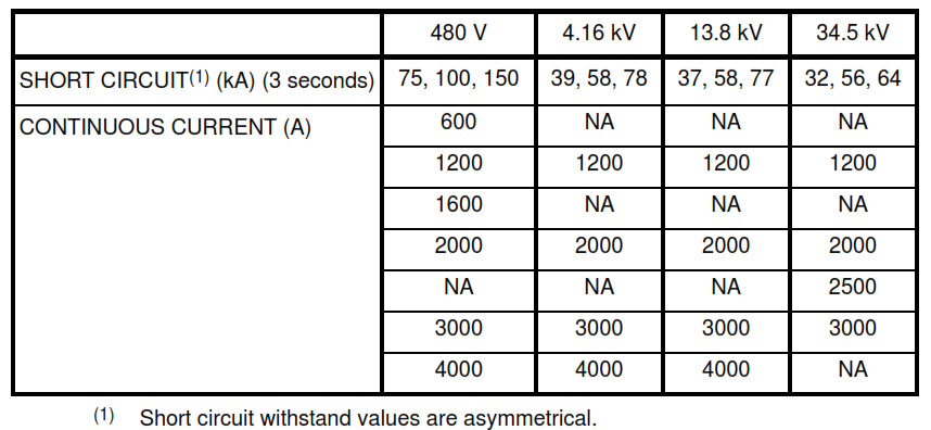
- Continuous self cooled current and short circuit withstand ratings shall comply with the following:
- The hottest-spot total temperatures of the various components of the bus duct shall not exceed the values in ANSI C37.23 under actual site conditions (50 °C ambient with direct solar radiation). Forced
cooling shall not be used for any rating without specific approval from company.
Bus Bars and Bus Ducts Enclosure
- The bus duct shall be a totally enclosed non-ventilated construction.
- The enclosures for bus shall be NEMA 12 gasketed for indoor sections, and NEMA 4X (water-tight, dust-tight and corrosion resistant) for outdoor sections.
- Outdoor enclosures shall have a sloped top that prevents collection of water. Joints shall be water tight by design and not dependent on the gasketing material for water tightness.
- Enclosures shall have removable covers for access to bus bar joints and other internal devices. Access openings in horizontal sections shall be located on the bottom of the enclosure. Covers for access
openings shall have neoprene gaskets and captive fasteners. - Enclosure for bus assemblies with a current rating less than 2000 A shall be made from No.11 gage steel as a minimum. For bus duct with a current rating of 2000 A or greater, all or part of the enclosure
shall be made from non-magnetic metal, to limit induced current losses and circulating currents by breaking the magnetic path. - The bus duct enclosure shall be electrically continuous. Suitable connectors shall be furnished to bond the enclosure (or ground bus) of the bus duct to the ground bus or ground terminal of the equipment to ensure continuity of the equipment grounding circuit between the connected equipment.
Bus Bars
- The bus bars shall be fabricated of 99 percent pure copper. The contact surfaces at joints shall be silver plated.
- Bolted bus bar connections shall be made with the bolts passing through the bus bars in a way that they can be properly torqued and locked in place to maintain full and uniform pressure under all operating conditions. Torque requirements in N.m shall be furnished by vendor.
- Temperature rise of bus bar joint shall not exceed bus bar rise by more than 5 °C; and in no case shall such bus bar joint temperature rise exceed 55 °C above ambient of 50 °C (105 °C total temperature).
- Bus bar and joints shall be manufactured to remove sharp edges, and to minimize corona. Joints shall be covered with formed insulating boots.
- Bus bars shall be insulated with flame-retardant, non-hygroscopic insulating material rated for continuous operation at 120 °C.
- Suitable connectors shall be furnished to bond the enclosure (or ground bus) of the bus duct to the ground bus or ground terminal of the equipment, to ensure continuity of the equipment grounding circuit between the connected equipment.
- The design shall accommodate expansion/contraction of the bus bars and housing due to temperature changes.
Bus Bar Supports
- The bus bars shall be supported to withstand the rated short circuit current.
- The bus supports shall be a flame-retardant, track-resistant and non-hygroscopic material. Supports shall be manufactured from the materials listed below:
Building Penetrations for Bus Bars and Bus Ducts
Flame-retardant and vapor-resistant barriers shall be furnished for all penetrations of interior and exterior walls and floors. The barrier shall have a flame rating of 1 hour minimum. A metal flange shall be provided for each penetration, to ensure a secure connection between the outside of the bus duct enclosure and the wall or floor.
Hardware
All external fasteners on enclosures located outdoors shall be made from series 300 stainless steel.
Bus Bars and Bus Ducts Space Heaters
For bus duct rated 600 V and above, both indoor and outdoor bus sections shall be equipped with space heaters. Screened breather-drains shall be provided in the bottom of the enclosures. Space heaters shall be rated 230 V but shall be operated at 115 V. The heaters shall be thermostatically controlled, with the supply connections in a junction box at the switchgear end of the bus duct.
Connectors
- The bus duct shall be provided with flanges for securing the housing to the transformer on one end, and to the switchgear or motor control equipment on the opposite end.
- Flexible connectors shall be included for connection of the bus bars to the equipment terminals. The connections shall be inline and in the same plane with the terminals. Twists or offsets not acceptable in the flexible connectors.
- All material for the connections (for both terminations and bus section splices), including splice plates, bolts, washers, nuts and insulating materials, shall be furnished and shipped with the bus duct.


