This article establishes guidelines for use of capacitance level measurement.
Capacitance Level Transmitter Principal
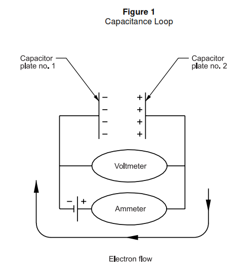
A capacitor consists of two conductors separated by an insulator. The conductors are called ‘plates’ and the insulator the ‘dielectric’. Capacitors are able to accept and store an electric charge. When a capacitor is connected to a battery (Figure 1), the electrons on plate No. 2 are attracted to the positive electrode of the battery, and the electrons on plate No. 1 are repelled by the negative electrode of the battery. The electrons flow until the battery potential is established across the capacitor. The larger the capacitor the more current will flow to charge the unit.
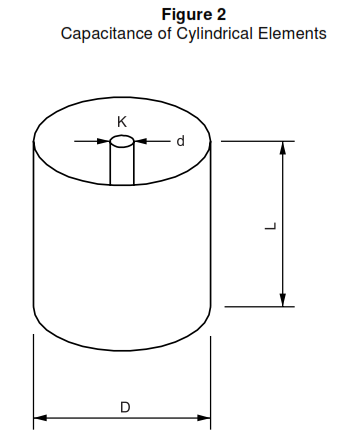
Capacitance. The farad (F) is the basic unit of capacitance and represents a charge of one coulomb (C) when connected to a one-volt source. This is a large unit, so the microfarad (f) and picofarad (pf) are usually used. The electrical size of a capacitor is affected by its physical dimensions and the material (dielectric) between the plates. The relationship of these factors for a cylindrical capacitor is shown in
Figure 2.
- The capacitance of two or more capacitors connected in parallel is equal to the sum of the individual capacitances. When connected in series, the reciprocal of the total capacitance equals the sum of the reciprocals of the individual capacitances.
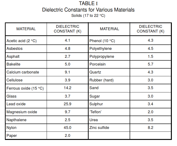
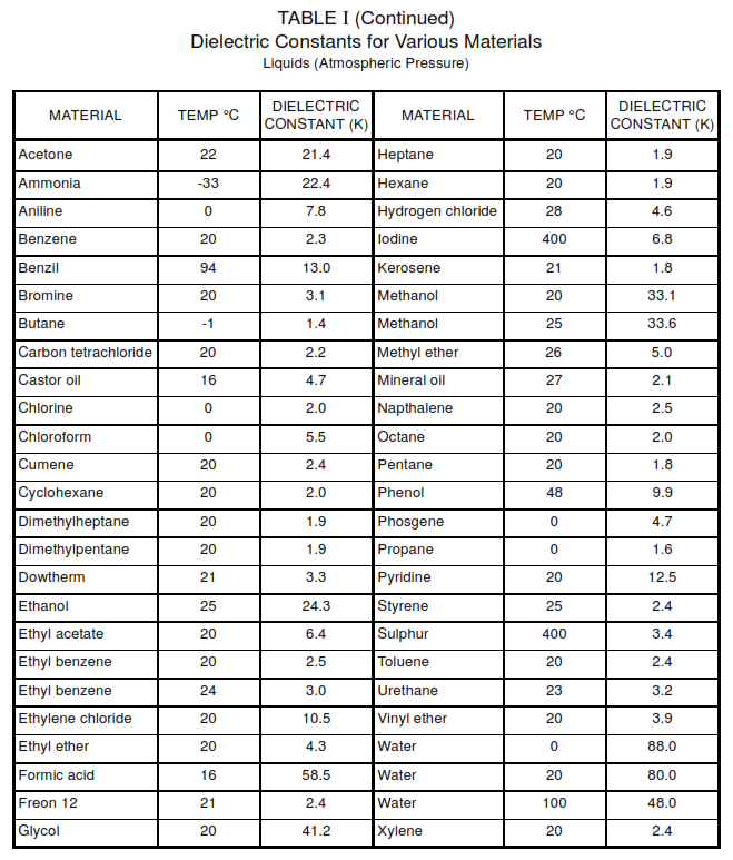
- Dielectric Constant. For a vacuum, the dielectric constant is 1.0. For pure materials, the dielectric constant is a fundamental property. The relationship between the dielectric constant of a binary mixture and the percentage of one of the ingredients has to be established experimentally. Table I , lists dielectric constants for a selected group of materials.
- A change in the characteristics of a material will be accompanied by a change in dielectric constant, which is often larger, more definite, or more easily measured than changes in other properties. Process material variations, which are accompanied by dielectric constant changes, influence the accuracy of level measurement and shall be carefully evaluated. Examples of these variations are:
- Temperature Effects. As the material temperature increases, its dielectric constant decreases. Temperature coefficients are in the order of 0.1 percent per degree Celsius. Automatic temperature
compensator units can be installed to negate the effect of temperature variations if temperature coefficients are known or can be measured on-line. - Chemical and Physical Effects. Chemical and physical composition and structure changes affect the di-electric constant. Water has a high dielectric constant, so variations in moisture content of the measured material will have a pronounced influence upon the dielectric constant.
- When the dielectric constant of solids is measured, it should be noted that variations in the average particle size and changes in packing density will affect the dielectric constant. Laboratory tests are usually required to determine these effects.
- Temperature Effects. As the material temperature increases, its dielectric constant decreases. Temperature coefficients are in the order of 0.1 percent per degree Celsius. Automatic temperature
Capacitance Level Transmitter Theory and Operation
- In capacitance probe installations, variations in level cause changes in capacitance. Capacitance is usually measured by a bridge circuit excited by a high-frequency oscillator (0.5 to 1.5 MHz). The probe is insulated from the vessel and becomes one plate of the capacitor. The other is the vessel which is electrically bonded to the instrument. The material between the two is the dielectric. As the level rises, vapors with low dielectric constants are replaced by the higher dielectric constant process materials. The capacitance increases linearly with level, and is detected by an instrument calibrated in units of level.
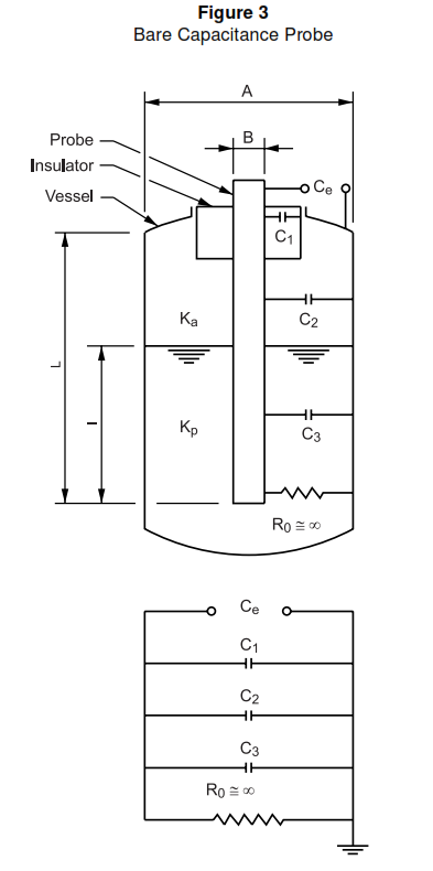
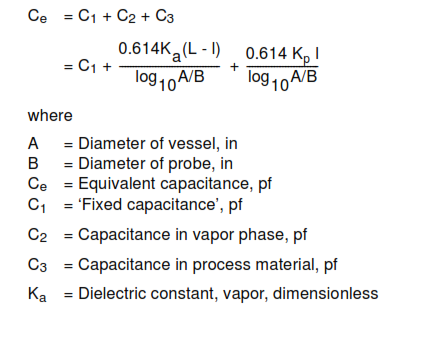
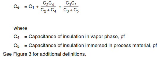
- Nonconductive Materials. In addition to insulated probes, the bare metal probes, as shown in Figure 3, can be used for measuring the level of nonconductive materials (conductivity less than 0.1 micromho per centimeter). C is the fixed capacitance of the system caused by, for example, tank/probe geometry, and cable capacitance, and is unaffected by level changes. R is the effective resistance between the probe and 1 the vessel and varies with the level in the tank. If the value of R cannot be approximated as infinity (such that C e = C 1 + C 2 + C 3), the measurement cannot be made with a bare probe. The capacitance of the system should only be affected by changes in Ievel only; therefore, the probe position and size, and the dielectric constant of the process material, has to remain constant.
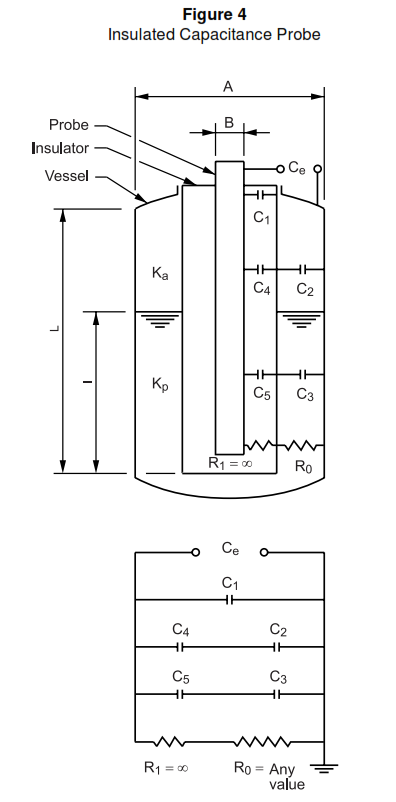
- Conductive Materials. For measuring the level of conductive materials (conductivity usually greater than 20 micromhos per centimeter), insulated (normally Teflon coated) probes are used (Figure 4). With a properly applied insulated probe system, the measurement is largely unaffected by the fluid conductivity and, therefore, this probe design is applicable to conductive or nonconductive materials. However, the fluid conductivity must be considered when applying a specific system.
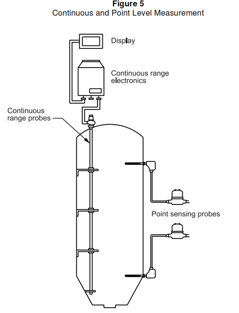
- Point or Continuous Level. The change in capacitance can be used to detect a point level or a continuous level (or both). The electrode configuration can be a vertical probe for continuous measurement
or a side-entering probe for point level measurement (Figure 5). A side-entering probe has a higher sensitivity and reproducibility for point level detection.
Complications
- Limited Detection Sensitivities. If the capacitor formed by the electrode-vessel-fluid has a small capacitance compared to the cable capacitance connecting the system to the electronics, the achievable
span may be inadequate for the application unless compensated. The electric cable from the measuring capacitor to the electronics can be compensated for by a parallel dummy cable of identical construction installed in the same geometry and environment as the measuring system cable. This allows the system to place these two capacitances on opposite sides of the bridge in a similar fashion to four-wire resistance thermometers. - Dielectric Variability. The problems associated with capacitance-level measurement are directly attributable to the physics of the observed phenomenon. Since the vessel and the probe do not usually
change dimensions, certain of these are associated with:
a. Coating of the probe by the material being processed
b. Variable dielectric over the length of the probe
c. Variable dielectric of the total mass due to variations in temperature, composition, and solids packing density - The most serious problems arise when the probe remains coated with the material being measured. If this coating is a conductive path to the wall or the main body of the liquid, the capacitance measuring system indicates a higher level than exists. If the coating is nonconductive, the interference with measurement accuracy is much less pronounced. For some applications, a proprietary technique is available which can differentiate between a probe coating and a liquid level change. In a continuous application, where material being measured changes in dielectric constant or conductivity (or both), a special design called ‘True Level’ is available from Drexelbrook. The design uses a second probe which is always emersed in the process fluid, to sense any electrical property variation. Special electronics compensate the primary level probe for these variations. The system requires that the material in the vessel be homogeneous in composition so that both probes ‘see’ the same electrical properties, making it usually unsuitable for measuring granular products, and never suitable for measuring interfaces.
Proximity Sensing
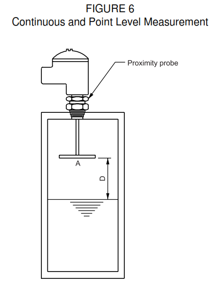
- Capacitance measurement can also be made without contacting the process material. For example, a plate suspended above a liquid surface can be used to provide a reproducible nonlinear signal indicating proximity of the level to the sensor, where the liquid:
a. Tends to coat
b. Is too hot (for example, glass melt)
c. Is on a belt
d. Foams or is not homogeneous
Installation of a proximity probe is illustrated in Figure 7. Level variations change the capacitance between the sensing plate and the material surface. - The use of a proximity probe eliminates the need for isolating media, for example purge gases and diaphragm seals. It can also be used as a redundant level sensor for backup purposes on point level applications. The device is available both as a high level switch or as a continuous level detector. It is not practical as a low level switch unless the distance between high and low level settings is small.
- The relationship between the distance from the sensing plate to the material surface, and the area of the sensing plate is very critical. The minimum proximity plate area can be determined by using the following equation (see Figure 7):
- The equation is applicable for continuous proximity-type capacitance level measurement if the process material is conductive (greater than 20 micromho per centimeter).
Electrical System Considerations
- Hazardous Area Installation. Most cable and probe systems can be furnished in an intrinsically safe configuration. The electronics will require either a suitably classified supply or an explosion-proof housing.
- Calibration. Calibration is best performed with the actual fluid at operating conditions. An electrical calibration using substitution capacitors can be performed but relies on prediction rather than observation.
- Correct bonding of the instrument to the vessel is essential as resistance in the process connections, for example ‘Teflon’ tape, can cause erroneous readings.
Capacitance Level Transmitter Advantages
- A simple system with a direct insertion probe can measure level under severe temperature and high pressure.
- Impulse element lines and diaphragm seals are not required for severe service.
- The inherent differences in dielectric constant between phases can make interface level detection feasible.
Capacitance Level Transmitter Disadvantages
- If the dielectric constant or adhesive or coating properties of the material are variable, an alternative method is advisable.
- Measurement of solids can be complicated by the presence of fines in the air while a silo is being filled. In addition, if the silo is constructed of a nonconductive material, for example fiberglass, the presence of a considerable electrostatic charge between the silo and the particles being fed can destroy the apparatus.
Capacitance Level Measurement Precautions
- Information about the dielectric properties of the material and the construction of the vessel should be given to the vendor to minimize failures.
- A major problem in applying these devices is variation in the dielectric constant. In more difficult applications, multiple lab samples should be run at various process conditions to define the expected variations.
- The capacitance units operate at radio frequencies, so care shall be taken to avoid RF pickup by the device. RF pickup is primarily through sensor leads, signal leads, or the probe if it is installed in a nonconductive vessel. Interference can be minimized by installing the leads in conduit and having a metal vessel. If operation of a walkie-talkie is expected in close proximity to the device, for example for communication during calibration, then special RFI filters shall be specified.
- Sensitivity and drift in the instrument should be carefully considered. Some devices are sensitive only to 0.5 pf and will drift 5 pf due to a tem-perature change of 55 °C (100 °F). The best quality units available are sensitive to 0.1 pf and will drift only 0.2 pf per 55 °C (100 °F) change.
- The possibility of measurement error caused by fluid property changes makes it advisable to provide a redundant Ievel switch for alarm or interlock functions on hazardous application.
- The mechanical installation shall follow good structural and electrical practice. Manufacturers supply recommended mounting practices which shall be carefully reviewed for adequacy, and followed in detail.
- In hazardous applications, a thorough investigation and evaluation shall be made of the vendor’s probe seal design. Seal failures have occurred as a result of poor design and over-temperature excursions.
- In applications where the process fluid might cause the probe to bend or move about, the measurement geometry shall be maintained by proper support of the probe.
- Probe insulator requirements are determined by the process pressure and temperature. Corrosion conditions determine the most desirable probe coating. The coating conductivity is typically less than 0.1 micromho per cubic centimeter.
