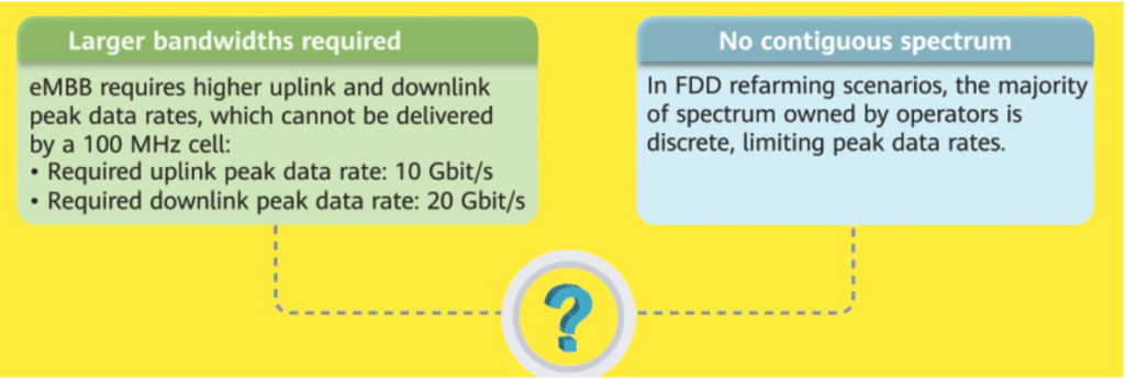
Enhanced Mobile Broadband (eMBB) is a critical 5G application scenario enabling high-data-rate services like 2K/4K video streaming and AR/VR. To achieve the exceptionally high downlink peak data rates required by eMBB, bandwidth plays a crucial role. Similar to wider roads accommodating more vehicles, larger bandwidths allow more data transmission, enhancing peak rates. However, contiguous large bandwidths are challenging to acquire. To address this, operators can aggregate discrete spectrum segments to deliver faster data services, maximizing resource utilization and boosting eMBB performance.
Definition
Carrier Aggregation (CA) is a technique in LTE and 5G networks that combines multiple contiguous or non-contiguous carriers to expand bandwidth and boost uplink and downlink peak data rates. This also addresses the challenge of fragmented spectrum by optimizing the use of discrete spectrum allocations.
Key Terms:
- PCell: Primary cell where the CA UE is anchored.
- SCell: Secondary cell configured via RRC messaging to provide additional resources.
- CC: Component carriers aggregated for a CA UE.
- PCC: Primary component carrier of the PCell.
- SCC: Secondary component carriers of SCells.
For CA, the coverage of PCell and SCells must overlap to enable seamless data transmission across multiple carriers. Common scenarios include enhancing capacity and coverage in high-demand areas.

lntra-gNodeB carriers with one providing edge coverage for another.

lntra-gNodeB different coverage carriers.

lntra-gNodeB co-coverage carriers.

CA Types.
Carrier Aggregation (CA) can be categorized based on the relationship between the frequency bands of component carriers (CCs). These types include:
| CA Type | Support in FR1 | Support in FR2 |
Contiguous intra-band CA. | TDD-only: 2CC in both the uplink and downlink. FDD+ TDD: not supported. FDD-only: not supported. | 4CC in both the uplink and downlink. |
Non-Contiguous intra-band CA.  | Not supported | Uplink: not supported. Downlink: 2CC. |
Inter-band CA. | TDD-only: 2CC in both the uplink and downlink. FDD+ TDD: not supported in the uplink; 2CC in the downlink. FDD-only: not supported | Not supported. |
Key Technologies
Key technologies in SCell management for Carrier Aggregation (CA) include:
- SCell Configuration: Adds new secondary cells to UEs.
- SCell Change: Switches UEs to secondary cells with better signal quality.
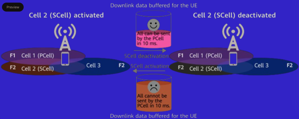
- SCell Activation/Deactivation: Only activated SCells can handle data. Deactivation disables data transmission and reception until conditions improve.
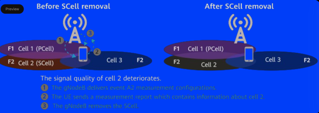
- SCell Removal: Removes SCells when their signal quality falls below the A2 event threshold for CA.
- SCell Uplink Timing: Ensures uplink performance with independent timing advances (TAs).
- SCell CSI-RS Beam Scheme: Uses beam sweeping for accurate CSI reporting in asymmetric CA setups.
1. SCell Configuration.
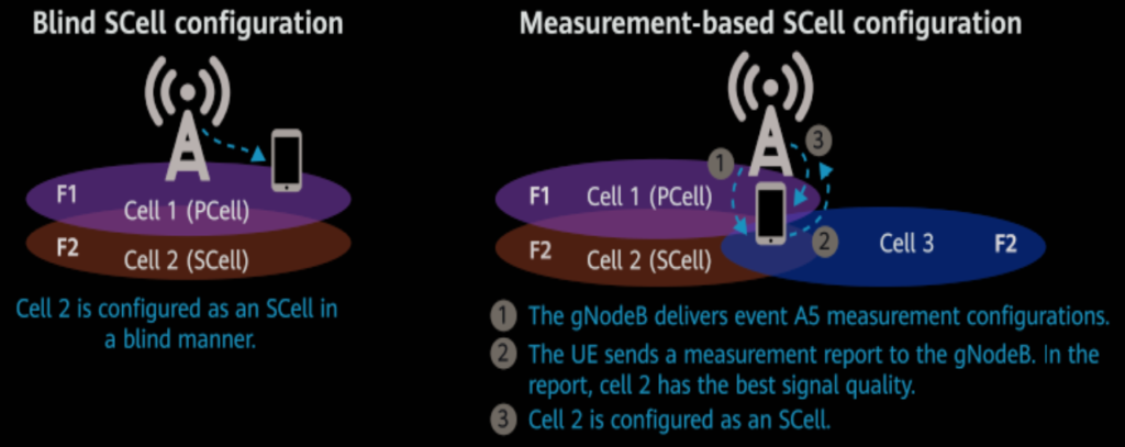
SCell configuration for Carrier Aggregation (CA) is initiated during initial access, handovers, or RRC connection reestablishment. Frequencies for CA must be preconfigured, and the gNodeB selects cells sequentially from the set until the SCell limit is reached.
- Blind SCell Configuration: Performed without measurements; suitable for co-coverage scenarios within the same gNodeB. It requires a specific configuration switch.
- Measurement-Based SCell Configuration: Used in scenarios with varying coverage or edge conditions; relies on signal measurements for SCell selection.
Blind configuration is preferred for efficiency in co-coverage, while measurement-based configuration is more robust for complex coverage differences.
There are two Scells configuration modes. 1. Blind Scell configuration modes. 2. Measurement based Scell configuration modes.
2. Scell Change.
SCell change is a mechanism to maintain optimal signal quality for UEs in a Carrier Aggregation (CA) scenario. If an intra-frequency neighboring cell offers better signal quality than the current SCell, the gNodeB evaluates this new cell for SCell replacement.
Upon receiving a UE’s measurement report, the gNodeB prioritizes cells in the report based on signal quality. It attempts to configure the highest-quality cell as the new SCell. If the configuration succeeds, the SCell is updated; otherwise, the gNodeB retains the existing SCell configuration.

1. The gNodeB delivers event A6 measurement configurations.
2. The UE sends a measurement report to the gNodeB. In the report, cell 3 has the best signal quality.
3. The SCell is changed to cell 3.
3. SCeII Activation/Deactivation.
SCell activation and deactivation in Carrier Aggregation (CA) are resource optimization mechanisms. Activated SCells consume control resources, so they are only activated when traffic volume is high, such as when the PCell cannot transmit all buffered downlink data within 10 ms. Conversely, SCells are deactivated during low traffic or when their CQI (Channel Quality Indicator) drops below a defined threshold. This dynamic adjustment ensures efficient resource utilization and optimizes system performance by balancing traffic demands and maintaining quality of service.
4. SCeII Removal.
SCell removal in Carrier Aggregation (CA) occurs when the signal quality of an SCell falls below the event A2 threshold as determined by measurements from the UE. Upon receiving a measurement report indicating poor signal quality, the gNodeB decides to remove the SCell to maintain efficient resource allocation and optimal service quality for the UE. This ensures that UEs operate with cells that meet the necessary quality standards for effective data transmission.
5. SCell Uplink Timing.
In uplink intra-FR inter-band Carrier Aggregation (CA), different timing advances (TAs) are used for the PCell and SCells because the distances between the CA UE and the antennas of these cells differ. If a common TA is used, uplink demodulation performance and peak data rates may suffer. To address this, the Multi-Timing Advance (MTA) function allows the gNodeB to maintain separate uplink timing mechanisms for each cell. This ensures that the UE sends uplink data using independent TAs, preserving uplink performance.


6. Scell CSI-RS Beam Scheme.
To enable downlink Carrier Aggregation (CA), the gNodeB must determine the CSI-RS beam directions for the UE in both the PCell and SCells. In asymmetric CA, some SCells are configured only for the downlink, preventing beam direction determination via uplink signals.
In intra-band CA, when the same RF module serves both the PCell and SCell, the PCell’s beam direction is applied to the SCell. However, for inter-band CA, where PCell and SCells use different RF modules, the gNodeB employs the CSI beam sweeping function to determine CSI-RS beam directions for SCells.
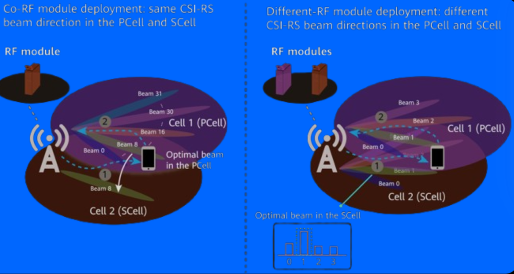
| The SCell uses the same beam information as that in the PCell and sends CSI-RSs on the beam that is shared with the PCeII. | The gNodeB performs CSI beam sweeping in the SCeII of a UE to obtain optimal beams for the UE in the SCell, and it sends CSI-RSs on these beams. |
| The UE performs measurements for CQI, PMI, and RI based on the CSI-RSs sent by the SCell. Then, the UE reports the measurement results of the SCell on the PUCCH or PUSCH in the PCell. | The UE performs measurements for CQI, PMI, and RI based on the CSI-RSs sent by the SCell. Then, the UE reports the measurement results of the SCell on the PUCCH or PUSCH in the PCell. |
What are networking requirements for CA in 5G?
Frequency requirements:
The frequency requirements for intra-band CA include the availability of at least two frequencies on the live network. The NRCellFreqRelation Management Object (MO) must be configured. In low-frequency bands, the spacing between the center frequencies of the carriers involved in CA must comply with specific requirements outlined in 3GPP TS 38.101-1. These requirements ensure proper channel spacing for carrier aggregation.
Coverage requirements:
For Carrier Aggregation (CA) to be effective, the coverage areas of the involved cells must overlap. The effectiveness of CA decreases as the overlap area shrinks, meaning a larger overlap results in a wider effective area for CA.
Cell requirements:
To ensure effective Carrier Aggregation (CA), certain cell requirements must be met:
- The NRCellRelation MO must be configured.
- PCI conflicts in intra-frequency cells must be mitigated.
- CA does not apply to low-frequency cells with short PUCCH.
- Intra-band CA requires the same TA offset for PCell and SCells; mismatch impacts uplink throughput.
- Intra-FR inter-band CA requires the frame offset difference between PCell and SCell to be ≤625 Ts, with a distance limit based on the offset formula to ensure downlink throughput.
For intra-FR inter-band CA, the frame boundaries of the PCell and SCell must be aligned in the uplink to avoid affecting the uplink throughput. Additionally, for DBS3900 and DBS5900 LampSites, the PCell and SCells must be served by the same RF module, although this requirement does not apply to other 3900 or 5900 series base stations.
How to activate CA at network?
1 .Turn on the CA switch.
2.Set CA-related parameters:
• Thresholds for events A2, A5, and A6.
• Blind SCell configuration switch.
• Blind-configurability of a cell.
• CQI threshold for SCell deactivation.