HOW TO CHECK FLOW ELEMENT, FLOW METER AND VORTEX METER
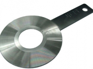
How to check Flow Element or Orifice Plate
- Ensure that surfaces are smooth and perfectly flat without scratching or bowing.
- The flow element shall be ensured that its data and material specification stamped on the data plate or tab handle agree with the specification.
- Where applicable, drain or vent holes shall be correctly positioned.
- The upstream and downstream edges of the orifice plate shall be checked to ensure there are no wire edges or burrs.
- The orifice and plate thickness shall be checked by micrometer/vernier caliper. Orifice bore shall be measured in four positions to ensure circularity. Calculate Beta=d/D ratio, where d=orifice diameter or bore diameter and D=pipe internal diameter and verify with specification sheet and stamping on orifice plate.
How to check Flow Meter
- Visual checking shall be carried out to ensure that the instrument has no damage. Tag number, size of the flange, and material shall conform to respective data sheet.
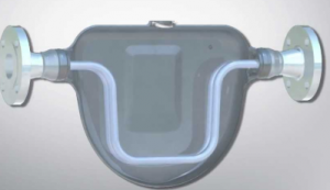
- For flow meters like turbine, positive displacement (P.D.) and coriolis, parameter input and/or configuration work shall be confirmed by connecting power supply to the instrument and record the parameters as per approved form.
- HART communicator shall be used for configuration check & testing.
- Flow elements such as magnetic flow meters, etc., which are not usually tested in the field shall be checked for its manufacturer’s test certificates.
How to check Vortex Meter
- Visual Check and smart transmitter configuration check shall be performed.
- Tag number, k-factor and design density shall be checked. Full tag no. shall be inputted into descriptor field.
- HART communicator shall be used for configuration check.
- After the test has been completed, the instrument shall be identified with a color code sticker.
- Result shall be filed and recorded on applicable forms as per approved Form.
Check more about please navigate our website for instrumentation calibration.

