This article is about COMPRESSOR MAP OF COMPRESSOR CONTROL SYSTEM and focusing to the engineers, technicians and supervisors. You will find lot of documents related to this article. Just navigate our website www.paktechpoint.com and find more articles. Please! Do not forget to subscribe our You tube channel also. Thanks in Advance.


COMPRESSOR MAP OF COMPRESSOR CONTROL SYSTEM
Standard Compressor Performance Map
The Standard Compressor Map is described by polytropic head, Hp, versus actual volumetric suction flow, Qa, and compressor speed, N, You can see in following figure. Depending upon the compressor configuration and instrumentation, changes in molecular weight, temperature, and compressibility are compensated for accurate representation of the compressor operation.

Standard Operating Point
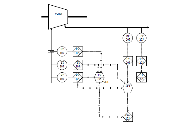
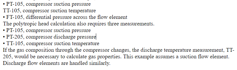
Here it can be seen that the volumetric flow calculation is carried out using three measurements. (The instrument tags are given as an example).
Overview of Compressor Control Functional Block diagram
Standard Surge Control Line
We normally program our compressor map in anti surge controller and data points from surge line are collected from the compressor map. Now question is What is surge control line SCL, The combination of surge line and safety margin line(user configuration as % of flow of surge).On SCL Line our limitation ends and we modulate anti surge control valve.
The Boost Line, or Backup Line, give more anti-surge protection. When the operating point (OP) reaches this line, a fixed response is triggered to prevent a surge.We can define here Boost Line is percentage of flow behind the Surge Control Line (to the left of).
The Surge Limit Line has series of maximum twelve operating X-Y (with maximum of twelve) points and programmed in controller. Compressor maps can be described in different units. The CCS supports the following compressor map unit entries:
• Discharge pressure versus actual flow, P2=F(flow)
• Pressure ratio versus actual flow, P2/P1=F(flow)
• Polytropic head versus actual flow, H=F(flow)
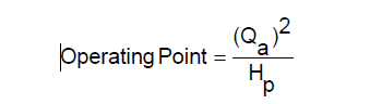
• Operating point versus reduced head, Q2/H=F(red head)
Occasionally the given compressor map is described in a different unit and will need to be converted.
Additionally, surge limits might be unproven or unknown, so it is sometimes desirable to determine the values used for the surge points by field mapping the compressor.
It is recommended that at least six points are entered. Points must be entered in ascending order, meaning that the lowest flow will be entered at point 1. Compressors typically have higher flow requirements with higher head values.
SYSTEM OVERVIEW AND CONTROL HARDWARE FOR COMPRESSOR CONTROL SYSTEM
OVER SPEED PROTECTION IN COMPRESSOR CONTROL SYSTEM
Anti-Surge Control Theory and Quench Control Theory of Compressor
Surge and Compressor Choke in Compressor Control System