This article is about Drilling and Installation of Monitoring Wells and Development and focusing to the engineers, technicians and supervisors. You will find lot of documents related to this article. Just navigate our website www.paktechpoint.com and find more articles. Please! Do not forget to subscribe our You tube channel also. Thanks in Advance.
PLEASE SUBSCRIBE OUR PAKTECHPOINT YOUTUBE CHANNEL
Drilling and Installation of Monitoring Wells
Two (2) groundwater monitoring wells will be installed at locations specified. Methods and procedures for these works will be consistent with Aramco Standard SAES-A-115.
The procedure will be as follows:
• Prior to start of drilling, the locations of the wells will be confirmed with site representative. A starter pit will be advanced by hand tools to 1.2m prior to drilling, however, clearance of services will be the ultimate responsibility of contractor.
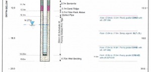
• The boreholes will be formed using a Rotary Wash Boring Technique to allow the installation of pipework of nominal 50mm internal, 63mm external diameter. A borehole log will be prepared for each location and an example borehole log is presented in Appendix A;
• Following completion of the borehole a 50-mm diameter UPVC casing and slotted sections of pipework will be installed down to the bottom of the hole. The screened section will be designed to straddle the resting water table so as to allow floating products (oils) to enter the well;
• After the 50-mm diameter uPV pipes are installed in the borehole, a filter pack of washed sand or pea size gravel (2mm to 4.75mm) will be poured into the borehole annulus. A 0.3m thick cushion will be poured between the bottom of the casing pipe. The filter pack will be poured from the bottom of the borehole to a depth approximately 0. ?Om above the top of screened (slotted) section.
Please read also: High strength, non shrink cementitious construction grout -CIVIL
• The level of filter pack will be checked by using a depth tape during the emplacement until there is no observable drop in the level of the filter material. The filter pack will be topped off to the desired depth and the volume of filter pack poured and the annular volume will be compared to verify proper emplacement of filter pack. In general two bags of filter pack (with a 50 kg mass each) filled about 1.5m height of the annular space between the HOPE (with 63mm OD) and the hole size. The density of the sand is 1.6 Mg/m3 and therefore the effective diameter of the hole is about 230mm.
• Sand/bentonite pelleUball seal will be poured immediately above the filter as the lower part of the sanitary seal to about 1.4 meters above the slotted section. The level of the top of the bentonite seal will be checked by depth tape. Adequate time for hydration of the bentonite pellets will be allowed before sealing the remaining annulus.
• Cement with approximately 5% bentonite mixed with in-situ soil will be used to complete the upper seal. The cement mixture will be tremied from the top of the bentonite to the ground surface.
• Locking, above ground well covers with concrete pads set to a grade will be installed at each well location (PVC casing pipe and four ‘protection’ or ‘guard’ posts) to minimize the potential .
An example of as built construction details of each monitoring well is shown here
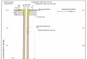
Notes:
1. Slottecl and blank PVC pipes are flush threaded.
2. Crash barriers are ollernately painted with yellow and black stripes.
3. Groundwater level and subsurface conditions shown above were based on Well Log of
4. Well construction based on the subsurface conditions encountered during drilling and sampling of boreholes.
Well Development
Well development will be undertaken using an air-powered top-loading submersible well development pump), which will deliver water to the surface through polyethylene (PE) tubing. Water recovered will be placed to ground. If alternative disposal is required, this will be the responsibility of contractor.
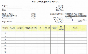
The development procedure is to discharge water from the well bore until non-turbid groundwater is being removed and key indicator parameters are stabilized. These include: pH, specific conductance, dissolved oxygen (DO), oxidation-reduction potential (ORP), temperature and turbidity. The groundwater parameters will be recorded regularly during development and submitted as part of the well-installation report.
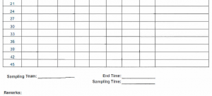
A well-development form is
EQUIPMENT Used in Drilling and Installation of Monitoring Wells and Development
The equipment and vehicle to be mobilized and utilized for the well installation and development will include the following:
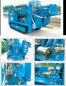
• 1 pc Hanjin Power 4000 SD rotary rig
• 1 unit Silverado double cabin pickup, (4×4)
• 1 unit Toyota Hilux, double cabin, 4×4
• 1 pc Groundwater measuring probe (YSI)
• 1 pc Peristaltic pump, (Solinst)
• 1 pc Oil water interface probe, (Heron)
• 1 pc Turbidity meter, (La Motte)
• 1pc Standards for pH, turbidity and conductivity
Photos of Drill Rig
