This article is about the design and application requirements for electrical heat-tracing system in order to maintain the specified temperature of process piping and analyzer system and to prevent the formation of condensation. Main keywords for this article are Electrical Heat Tracing Installation, Electrical Heat Tracing Application, Electrical Heat Tracing Design, Electrical Heat Tracing Material Selection.
Electrical Heat Tracing References
Institute of Electrical and Electronic Engineers (IEEE)
515 Recommended Practice for the testing, Design, Installation, and Maintenance of Electrical Resistance Heat Tracing for Industrial Application
National Fire Protection Association (NFPA)
70 National Electrical Code
496 Standard for Purged and Pressurized Enclosures for Electrical Equipment
-
Electrical Heat Tracing Application Considerations
Electric Tracing
Electric tracing shall be used when the following conditions exist:
a. Precise temperature control is required.
b. Steam supply is tight.
c. Tracing elements are not exposed such as under or in tank foundations.
Safety Design Considerations
The following safety items shall be included in the design of electric heat- tracing systems:
a. All electrical heat tracers shall be protected by a continuous metal sheath, wire braid, or cover which is to be grounded. Where wire braid is used, copper is required for ease of handling and ground fault capacity.
b. A ground fault protective circuit breaker, type to trip at 30 mA ground fault current, or other ground fault protection circuitry, shall be used on each heat tracing circuit at 120 volts, 208 volts or 240 volts.
c. For higher voltage circuits, a ground fault protective device shall be installed to de-energize the circuit at a value of ground fault current that is less than that required to operate the overcurrent protective device on the supply circuit.
d. When possible, one side of heat-tracer service should be grounded.
e. Electrically traced systems shall be marked conspicuously with commercially available signs, located outside the thermal insulation at approximately 3meter (10-ft) intervals.
f. Lockout provisions for system maintenance shall be provided.
g. Voltage on heating circuits shall be limited to 120 Volts to ground, except in special cases where it is advantageous, such as long lines, 480 Volts may be used on a line providing the following:
(i) The voltage to ground does not exceed 277 Volts.
(ii) The signs are installed to specifically note that the circuit voltage is 480 Volts.
Hazardous area considerations
For Class I, Division 1; Class II, Divisions 1 and 2; Class III, Divisions 1 and 2, the heaters shall be approved for the class of area where they are to be located.
For Class I, Division 2, the heater shall comply with either 1, 2, or 3 below:
a. The heater shall be approved for Class I, Division 1 locations.
b. The heater shall not exceed 80 percent of the ignition temperature in degree Celsius of the gas or vapor involved on any surface that is exposed to the gas or vapor when continuously energized at the maximum rated ambient temperature.
c. If a temperature controller is not provided, the heater shall not exceed 80 percent of the ignition temperature in degree Celsius of the gas or vapor involved on any surface which is exposed to the gas or vapor when continuously energized at 120 percent of rated voltage at the maximum rated ambient temperature.
Sheath temperature
The sheath temperature is defined as the pipe temperature plus the difference in temperature (ΔT) between the heater sheath and the pipe necessary to transmit the wattage being generated by the heater.
Sheath temperature shall be calculated for single conductor resistance wire, self-limiting cables and MI cable. Calculation can be performed using manufacturers heat trace material tables and guidelines by the manufacturer or with calculation software provided by heat trace manufacturers.
Calculated sheath temperatures shall be used to select the heater cable. Extreme care must be exercised in the selection of heater cable. To comply with the National Electrical Code, the manufacturer furnished “T” rating on the cable shall be less than or equal to 80 percent of the ignition temperature of the gas or vapor that causes the area to be classified.
Main keywords for this article are Electrical Heat Tracing Installation, Electrical Heat Tracing Application, Electrical Heat Tracing Design, Electrical Heat Tracing Material Selection.
Electrical Heat Tracing Design
The sections below provide the design data to facilitate the application of electrical heat tracing systems.
Heat Trace System
- Electrical heat tracing is generally used for one of the following:
a. Maintain fluid temperature within a pipe between low and high limits.
b. Maintain temperatures of analyzer tubing, process instrument tap lines to prevent condensate formation or maintain temperature limits.
c. Maintain temperature of cold tank foundation to prevent foundation breakdown. - The design of electric heat tracing systems shall consist of the following steps:
a. Calculate temperature differential.
b. Calculate heat loss for item to be traced.
c. Calculate insulation compensation.
d. Determine appropriate type of heat tracing to be used.
e. Calculate thermal output of heat tracing system.
f. Select voltage for heat tracing system
g. Select type of heat tracing cable to be used.
h. Select type of control to be used for heat tracing system.
To prevent a change of temperature or state (or both) requires a heat-tracing system with the capacity necessary to make up heat losses to ambient. Such a system will not add heat to the system except as a side effect if the system temperature is not controlled. The amount and type of tracing system is determined by the following steps:
Step 1. Determine temperature information for each tracer system. This is to include maximum and minimum operating temperatures, maximum temperature system may reach in case of upsets, minimum and maximum ambient temperatures expected, withstand temperature of thermal insulation, and the minimum auto-ignition temperature of fluids that may be present in hazardous areas.
Step 2. Determine pipeline information for each tracer system. This is to include pipe size(s), pipe schedule, pipe material, estimated length of tracer, number of pipe fittings (valves, flanges, etc), and the type of piping (welded or flanged) system.
Step 3. Determine thermal insulation system for each tracer system. This is to include type, thickness, thermal conductivity, and method of waterproofing.
Step 4. Determine one or several types of tracing systems to be evaluated. Since installation and maintenance of each type of system requires special skills and training, it is advisable to limit types used on any project to one or
two at most.
Step 5. Losses in each tracer system must be determined. Tables may be used for estimating watts lost per foot of pipe or pipe fittings
Step 6. Determine what individual heat tracer from types selected in Step 4 best meets the requirements from tracing manufacturer’s information. If selflimiting cable is selected for use, select the highest wattage, highest temperature cable available from the selected manufacturer. This approach is recommended for process heating and condensate protection, except for plastic. The additional cable costs are more than justified by the reduction of risk of cable failure.
Step 7. Determine ampere and voltage requirements for each heat tracer. This can be done from tracing manufacturer’s information.
To raise temperature or change of state (or both) requires a heat-tracing system to replace losses to ambient and add heat to process. The amount and type of tracing system is determined by the following steps:
Step 1. Determine temperature information for each tracer system. This is to include applicable information from the following: initial or entrance temperature, maximum and minimum operating or exit temperatures, maximum temperature system may reach in case of upsets, melting temperature, vaporization temperature, minimum and maximum ambient temperatures expected, withstand temperature of thermal insulation, and minimum ignition temperature of vapors that may be present in hazardous areas.
Step 2. Determine process fluid information for each tracer system. This is to include, where applicable, the low rate, density, specific heat, heat of fusion, heat of vaporization, and time available for heat up.
Step 3. Determine pipeline information for each tracer system. This is to include pipe size(s), pipe schedule, pipe material, pipe density, pipe specific heat, pipe capacity for process material, estimated length of tracer, number of pipe fittings (valves, flanges, etc), and the type of piping (welded or flanged) system.
Step 4. Determine thermal insulation system for each tracer system. This is to include type, thickness, thermal conductivity, and method of water proofing.
Step 5. Determine one or several types of tracing systems to be evaluated. Since installation and maintenance of each type of system requires special skills and training, it is advisable to limit types used on any project to one or two at most.
Step 6. Determine capacity requirements for each heat tracer to raise temperature or change of state (or both).
Process Temperature Maintenance
A completely coordinated and integrated electrical process heat tracing system shall be provided for process, instrumentation and miscellaneous piping systems as determined by process engineering.
The purpose of the process heat tracing system is to maintain the temperature of process pipes, instrumentation and equipment within a specified range during exposure to the environmental conditions described in Section 3. In order to prevent liquid solidification or “tarring”.
In addition provide heat up and de-solidification capabilities as required and defined during the process design effort.
The process heat trace system shall provide heat to the outside of process piping, instrumentation and equipment; and each heating circuit shall be automatically controlled by means of an individual temperature controller connected to RTD sensors located on the outside wall of the pipe or equipment. Each circuit shall be provided with an individual dedicated RTD sensor.
Control Philosophy
Each temperature controller shall operate an individual contactor or solid state relay for energizing and de-energizing the heating circuit. Each contactor or relay and its associated controller shall be protected by a separate branch circuit breaker located in the power distribution panelboard. Each circuit must be capable of energizing, for test purposes, without panel entry.
For process heat tracing, each process line shall be provided with an individually monitored and controlled heater cable. Individual flow and no flow conditions shall be separately traced and controlled. Each line size variation within a flow condition may also require a separate control circuit. Pumps must be removable without affecting the suction and discharge circuit integrity. Pumps with maintain temperatures above 65 C (150 F) must have separate control circuits.
Process heat tracing for pipes shall include all in-line components. All flanges, pumps, valves, devices, supports and appurtenances shall be traced with appropriate additional lengths of heater cable as required by pertinent installation details.
In general, process instrument tap lines shall be manufactured pre-traced and insulated tubing bundles. A separately controlled heater cable shall be used for each instrument line. Individual block heaters shall be provided and separately controlled for each remote transmitter.
Hoppers, bins, tanks, filters, vessels and other such equipment which may be identified as requiring process heat tracing shall be considered to be a part of the system requirements. Where not identified as being furnished by others, the heating and insulation of this equipment shall be as recommended and designed by the Seller. Either heater cable or flexible pad type heaters approved by the user shall be employed, and the heaters for each item of equipment shall be from an individually controlled power circuit.
The heating for each item of equipment shall be powered and controlled from a separate circuit in the process heat trace panel. Providing power and controls for these items shall be considered to be a part of the system requirements.
Insulation for storage tanks and large vessels that are greater than 10 ft. in diameter shall be a vertical standing seam panel system.
Electrical Heat Tracing Material Selection
Selection of heaters – An electrical heat tracer is an assembly consisting of a resistance heating unit, an insulating covering, a grounded outer metal sheath or shield, and, in most cases, an outer jacket. The heating element assembly may be purchased in many forms such as cable, strip, tape, etc, and may be applied to pipes, valves, vessels, and other surfaces where heat tracing is required.
The principal limiting parameters in the application of heating cables, strips, and tapes are the following:
a. Maximum rated temperatures for the heater insulation and sheaths
b. Wattage requirements of the system to be traced
c. Electrical classification of the area with respect to environment
d. The temperature limitation of the material within the pipe, vessel, etc, that is to be heated.
Heater Cable Types
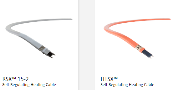
- Self-limiting heater cable is recommended for continuous operation under the following conditions:
a. Maximum voltage: 277 V rms.
b. Temperature range: Up to 120°C of maintenance temperature and 200°C withstand temperature.
c. Maximum wattage: 20 W/ft at 100°C (less on variations of type or temperature).
d. The heating element in this cable is a self-regulating conductive core between copper conductors with a large positive coefficient of resistance.
- The positive coefficient of resistance causes the heating element to produce significantly less heat as its temperature increases, to keep the cable and piping system from overheating, even when not controlled. It comes in various temperature, wattage, and voltage ratings and can be cut at any length up to a maximum without changing those ratings.
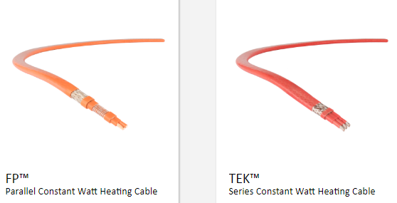
- Mineral lnsulated (MI) Cable Metal-sheathed tracing cable is recommended for continuous operation under the following limitations:
a. Maximum voltage: 600 V or 300 V rms depending upon the type.
b. High temperature applications where Temperature the range is as follows:
(i) Copper sheath up to 190C (370F) if sheath oxidation is to be avoidedand up to 250C (480F) if slow sheath oxidation is permissible.
(ii) Stainless steel sheath up to 420°C (800F).
(iii) Inconel sheath up to 593C (1100F).
c. Maximum wattage: Determined by sheath temperature limitations (see manufacturer’s catalog).
d. Type MI (mineral-insulated, metal-sheathed) cable should be considered for locations in classified hazardous areas and for operating temperatures higher than 1200C. The metal sheath of the Type MI cable provides a reliable and permanent ground under the most difficult or hazardous conditions. The seamless sheath and brazed joints are completely waterproof.
e. MI cable units assembled with approved explosion-proof fittings, explosion-resistant conduit boxes, etc, shall comply with the NEC requirements for installation in Classes I and II, Divisions 1 and 2 hazardous locations. The solid-type construction offers no air space through which flames, gases, or vapors can pass.
f. MI heater cable shall be procured as follows: - Complete cable assemblies with heating section of various lengths, cold sections, and compression end fittings, installed by the manufacturers.
Constant Wattage Heat-Tracing Cable
The constant wattage heat tracing cable shall not be used without the written approval of company.
Distribution Transformers
- Outdoor transformers shall be dry-type (unless specified otherwise in request for quotes and purchasing documents), and shall conform to applicable sections of Dry Type Distribution and Power Transformers Design Notes.
- Transformers shall be sized in accordance with the designed load, plus a minimum 25 percent spare capacity.
- A dedicated transformer shall be provided for each individual process heat tracing control panel. Each transformer shall be installed adjacent to its associated control panel.
Control & Monitoring Panels
Control panels shall be furnished to provide system control, indications and alarm functions.
Each control panel shall be assembled wired and tested in accordance with the requirements of SES E27-S01.
Main keywords for this article are Electrical Heat Tracing Installation, Electrical Heat Tracing Application, Electrical Heat Tracing Design, Electrical Heat Tracing Material Selection.
3. Electrical Heat Tracing Installation
Field Wiring Junction Boxes
- Field junction boxes may be used as required for collection of RTD temperature sensor wiring and heater power wiring circuits.
- Wiring for RTD circuits shall not be installed in same boxes with power or control wiring circuits.
- RTD wiring junction boxes and power wiring junction boxes shall be NEMA 4X stainless steel with full height hinged cover and mounting back panel. Boxes shall meet area classification and shall be sized as required to accommodate wires and terminals installed. A minimum of 20 percent spare terminals shall be provided.
- Terminals shall be rail mounted, modular type
- Nameplates and tags for junction boxes shall be in accordance with section
- Junction boxes shall be grounded per NEC Article 250.
- Suitable drains shall be provided for junction boxes.
Main keywords for this article are Electrical Heat Tracing Installation, Electrical Heat Tracing Application, Electrical Heat Tracing Design, Electrical Heat Tracing Material Selection.
Heater Power Connection and Splice Boxes
Unless otherwise specified, all heater power connections and splices shall be made in NEMA 4X junction boxes mounted outside of pipe insulation and jacketing. Power connection and splice junction boxes shall be installed on mounting brackets that shall be fastened to the pipe with 1/2 inch wide screw-down stainless steel straps.
All connections shall be made with 600 V free-floating, tubular screw pressure plate terminal blocks rated 35 amperes minimum. No more than two wires shall be connected on the same side of any terminal point. Termination of control and power wires shall be by lugs.
Boxes shall be grounded in accordance with NEC Art 250.
Control and Instrument Cable
- RTD’s shall be wired with 600 V, stranded copper, twisted triad, shielded instrument cable with 90C type FR-PVC outer jacket. Shields shall be aluminum-mylar with a stranded, tinned copper drain wire.
- Single triad instrument cables shall have 1.5mm2 conductors with 1.0mm2 drain wire.
- Multi-triad instrument cables shall have both individual and overall shields.
- Multi-triad cables shall have 1.0mm2 conductors with 0.75mm2 individual drain wires and 1.0mm2 overall drain wire.
Grounding
Each power circuit conduit shall contain a green insulated ground wire for grounding of all power junction boxes, heater power connection boxes and heater splice boxes. The ground wire shall be sized per NEC requirements, and shall be grounded to the control panel ground bus.
A separate grounding connection shall be provided inside each box. Ground connections shall be made with either a servit post type connector or by means of a screw tapped into the metal frame or enclosure. Ground connections shall not penetrate or weaken sealed enclosures approved for hazardous location and shall not compromise the specified NEMA enclosure standards.
Where screw type connections are used, ground wires shall be provided with ring tongue lugs.
The tinned copper braid on the self-regulating heater cables shall be grounded by connecting to the ground terminal inside the heater power connection and splice boxes.
RTD enclosures shall be grounded by means of the metallic conduit connections.
All conduit entries into control panel enclosures shall be bonded to the control panel ground bus.
4. Electrical Heat Tracing Drawing and Data Requirements
Listed below are items of essential data that will be furnished:
Isometric drawings shall be provided for each heat traced circuit. The drawings shall show the Extent of heat trace cable installation, Location of power connection terminations, Heater Circuit Identification number, Power circuit information including control panel or panel schedule ID and circuit number.
Outline and Arrangement Drawings – Outline and arrangement drawings shall be completely dimensioned and shall indicate the following:
a. Plan, front elevation, and other elevations, if pertinent.
b. Equipment arrangement.
c. Required clearances.
d. Location and size of all conduit entrances (top and/or bottom) for Purchaser’s connections.
e. Power cable terminator positions.
f. All terminal block locations including those for Purchaser’s connections.
g. Anchor bolt hole size, location and the recommended minimum anchor bolt size.
h. Ground connections.
i. Weight of equipment.
- Elementary Wiring Diagrams
- Elementary diagrams shall show all control devices and device contacts, each of which shall be labeled with its proper ANSI device function number.
- Terminals of all devices and terminal blocks shall be numbered.
- Connection Diagrams
- Connection diagrams shall indicate the approximate physical location of all items in each assembly.
- Connection diagrams shall indicate all wiring within each assembly and all interconnecting wiring between assemblies.
- Connection diagrams shall identify all terminals, terminal blocks, and wires.
- Connection diagrams shall clearly identify all wiring which is to be installed by the Purchaser.
Main keywords for this article are Electrical Heat Tracing Installation, Electrical Heat Tracing Application, Electrical Heat Tracing Design, Electrical Heat Tracing Material Selection.
