ELECTRICAL TEST LOW VOLTAGE POWER CIRCUIT BREAKERS
FIELD INSTALLATION TESTS
- Remove from the cell and inspect for physical damage and nameplate compliance with single line diagram.
- Remove arc Chutes and inspect for damage or missing segments.
- Verify arc splitter grids and ceramics.
- Inspect the breaker for defects or damage especially to insulation.
- Verify primary bushings, porcelains and finger clusters.
- Verify contact make and break.
- Verify for adequate electrical clearances.
- Verify mounting frame and all castings for cracks.
MECHANICAL INSPECTION
- Verify contact alignment over travel and contact pressure.
- Verify shunts and all brazed or soldered connections.
- Verify the operating mechanism for friction.
- Verify push rods, and the latch mechanism.
- Verify the trip mechanism latch load and sneak settings.
- Verify manual close, latch and trip operation.
- Verify trip free operation.
- Verify auxiliary switches for sequence, good contact alignment, and operating linkage.
- Verify terminal blocks and connections.
- Verify the mechanical condition of auxiliary devices, shock absorbers, bumpers, position indicators, latch Verifying switches , key lock out, etc.
- Verify alignment of secondary contacts of circuit breaker to cell.
- Verify for correct operation of shutters.
- Verify lock out mechanism operation of circuit breaker when installed in the cell.
- Verify that primary contacts are properly lubricated.
- Use a calibrated torque wrench to verify all bolted connections. Torque values per vendor’s specifications
- Withdraw the circuit breaker from the connected to the test and then fully withdrawn positions, verifying ease of movement between positions and that the breaker is trip free between the connected and test positions, and between the tested and withdrawn positions.
ELECTRICAL TEST LOW VOLTAGE POWER CIRCUIT BREAKERS
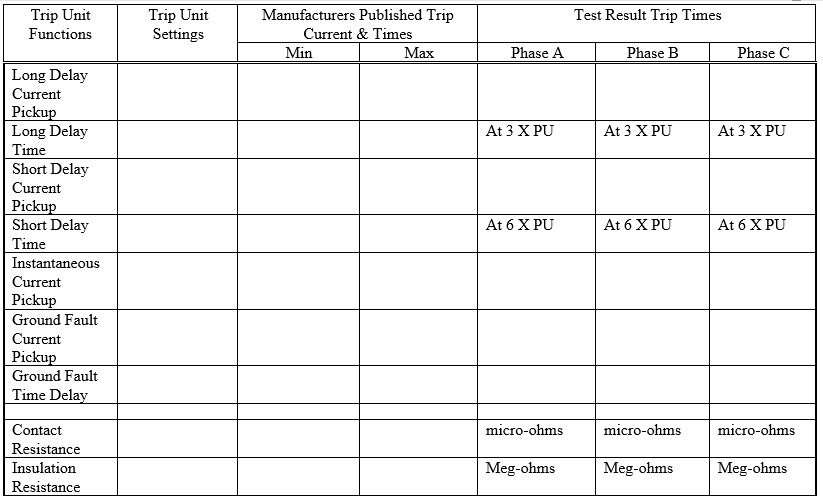
- Measure and record contact resistance. Investigate any values more than 200 micro-ohms or deviations more than 20%. Values must be consistent with those specified by the manufacturer.
- Perform an insulation resistance test with 1000 volt megger for one (1) minute from pole to pole and from each pole to ground and across open contacts of each phase.
- Verify minimum pickup current by primary current injection.
- Verify long time delay by primary current injection at three times (3X) current pick up.
- Short time pickup and time delay shall be determined by primary injection. Primary current injection at (6X) current pickup.
- Instantaneous pickup current shall be determined by primary injection.
- Trip unit reset characteristics shall be verified.
- Final protection settings shall be as specified by PDD protection engineering.
- Auxiliary protective devices, such as ground fault or under voltage relays, shall be activated to insure proper operation of shunt trip devices.
CIRCUIT BREAKER TEST DATA
| BREAKER TYPE | |
| BREAKER MANUFACTURE | |
| VOLTAGE RATING | |
| FRAME RATING AMPS | |
| TRIP UNIT RATING AMPS |
