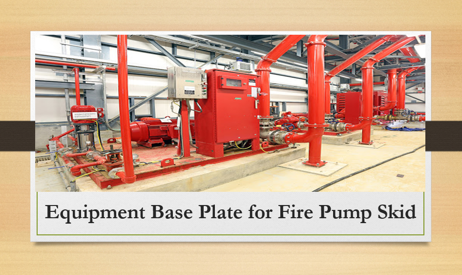
This article is about Equipment Base Plate for Fire Pump Skid and Following keywords for this topics are Pump base plate installation, its types and grouting Requirement, Pump base plate grouting procedure, pump base plate leveling, fire pump design guide, pump base plate leveling tolerance.
These are general instructions for construction of equipment baseplate for fire water pump installation.
Equipment Base Plate for Fire Pump Skid
- Fire water pump module base plate shall be made of fabricated steel or cast steel. The base plate shall consist of a system of longitudinal (long edge) and transverse (short edge) members and shall be designed to be supported on the foundation by grouting of the transverse members only. Transverse member spacing shall be maximum 4 m (12 ft) on centers.
- Base plate shall be designed for a four point lift. The selection of the main (full depth) members shall be such that the bending stresses of the longitudinal members are limited to 50% the yield strength of the material selected. The bending stresses for the longitudinal members shall be calculated using the total skid weight and shall be modeled using a simply supported beam under uniform loading. The maximum deflection shall be limited to L/9145 (L is the length of the longitudinal members in mm). For skids made in the US, the maximum deflections shall be limited to L/360 (L is the length of the longitudinal members in inches).
- Lifting lugs shall be welded or bolted onto the longitudinal members. Each lifting lug shall be sized for the total weight of the skid. The lifting lug load stresses (shear, bearing, bending, and tensile) shall not exceed the material allowable yield stresses. Material test certificates per the requirements of 4WGN-20001 shall be supplied for each lifting lug. Lifting instructions shall be provided together with a lifting diagram.
- The base shall extend full length to support all components supplied with the fire water system and shall give due consideration to adequate access for maintenance. Temporary bracing and other supports that might be required for shipment and/or lifting of the base plate shall be minimized.
- Base plates shall be provided with anchor bolt holes sized for 25 mm (1.0 in) minimum anchor bolts. The anchor bolt holes shall be provided at no less than 1.2 m (4 ft) on center starting a maximum of 0.6 m (2 ft) from the skid’s edge. A 20 mm (3/4 in) minimum vertical jack screw shall be provided 100 mm (4 in) adjacent to each anchor bolt hole to aid with leveling the base plate. Horizontal and vertical jack screws shall be provided on all major components to facilitate positioning and alignment.
- All mounting surfaces for rotating equipment base plates shall be fully machined, flat, and parallel. Surfaces shall be in the same plane within 150 micro millimetres/meter or 0.003 inches/foot in the longitudinal and transverse direction.
- Full depth structural steel members shall be prepared for continuous epoxy grouting with Philadelphia Resins Chockfast Red, or an Air Products approved equal. All exterior corners in contact with the epoxy grout shall have a 50 mm (2 in) minimum radius to prevent stress concentrations in the grout.
- The base plate shall be provided with checked (diamond) deck plate. Deck plates shall have 152 mm (6 in) fill holes with 13 mm (1/2 in) raised lip to facilitate filling with secondary cementatious grout. Sufficient 13 mm (1/2 in) vent holes shall be provided. If deck plate is placed such that water can pool on its surface, the skid shall have two DN40 (NPS 1 1/2) drain connections on opposite sides of the skid.
-
Base plate units shall be provided with two grounding (i.e., earthing) lugs, one at each opposite end of the baseplate.
- Supplier shall demonstrate to the Purchaser the levelness of the skid or support mounting surfaces. Levelness shall not exceed +/- 3 mm (1/8 in) total, based on starting at one anchor bolt location and proceeding to all others.
- Supplier shall also demonstrate to the Purchaser the squareness of the skid. Squareness shall not exceed +/- 3 mm (1/8 in) total, based on comparing the length differential of the skid’s exterior longitudinal and transverse members.
- Rotating equipment base plates shall be supported by longitudinal members tied to transverse members. In addition, the longitudinal members shall be cross braced with full size structural members at each end of the rotating equipment base plate. For rotating equipment with drivers 200 kW (250 hp) or above, an additional crossmember at the middle of the base plate shall be provided.
- Rotating equipment shall be level within 0.25 mm/m (0.003 in/ft) by placing a precision level at the equipment machined surfaces (mounting pads and / or pump casing flanges).
- For rotating equipment applications with power less than 200 kW (250 hp), equipment base plates shall be shall be bolted to module steel and gaps checked at each anchor bolt location prior to torquing. Gaps in excess of 1.0 mm (.030 in) shall be shimmed with a solid stainless steel shim.
- For rotating equipment applications with power greater than or equal to 200 kW (250 hp), base plates shall be mounted on adjustable chocks at each anchor bolt location after leveling with leveling screws. Supplier shall furnish the chocks from Vibracon or approved equal. Information (technical and ordering) on Vibracon can be found at www.vibracon.com or from the following.
Machinery Support, Inc. or Causeway Machinery Ltd.
109B 86th Street 70 Pier Road
Virginia Beach, VA 23451 Erith, Kent DA8 1TA
(877) 621-1777 Toll Free United Kingdom
(757) 417-7411 +44-1322-346346
Fire Water Pump Skid Requirement for Petrochemical Plant
