This article is a guide for use of float type level sensors in process plants. Main keywords for this article are Float Type Level Measurement. Float Switches. Level Indicator. Tank Gage Level. Solids Level Gage.Float Type Level Advantages.Float Type Level Disadvantages.
Float Type Level Measurement
- Floats are used as the energy source and the sensing part of a level measurement system, and also as the energy and sensing portion of a level switch. Floats may be very simple and inexpensive or may be part of a sophisticated, accurate system. In all cases, the float is exposed to the fluid or solid of interest, and has to withstand the pressures, temperatures, and chemical environment involved.
- Floats for higher pressures are often spherical in form.
Float Switches
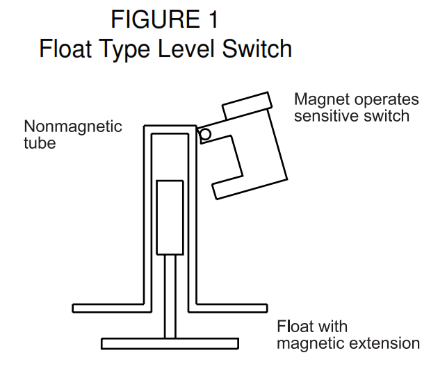
Float-actuated level switches are available from many vendors and in many styles. Most have electrical switches. See Figure 1. Some have pneumatic signals.
In each application, it is necessary to consider:
a. Whether the mechanism coupling the float movement to the switch will survive in the fluid environment. Many float switch failures are due to sticking or blocked moving parts. The surface of a
liquid will collect the foreign materials floating in the process and then deposit them on the instrumentation. Various kinds of magnetic coupling and other schemes are used to reduce this problem.
b. Whether the fluid has any waves or turbulence. If so, the switch may be cycled many times as the level approaches the actuation level, which may result in considerable wear.
Level Indicator
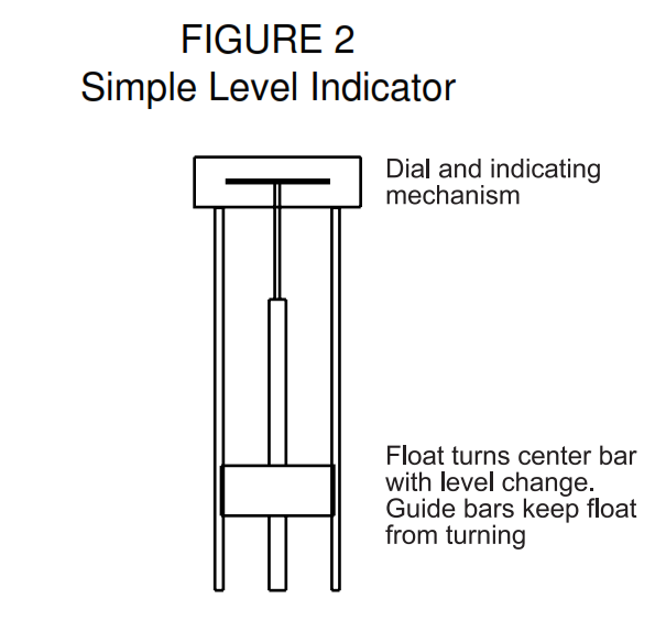
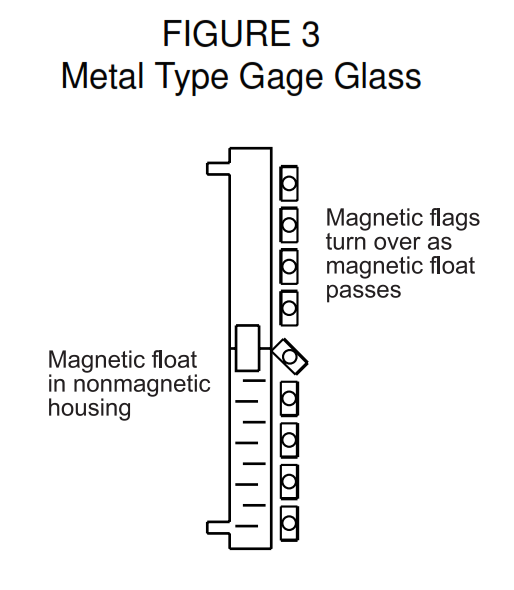
Float-operated level indicators range from the very simple and inexpensive, to metal tube replacements for gage glasses, with a magnetically coupled float moving an indicator, or causing colored flags to change orientation. See Figures 2 and 3 respectively.
Tank Gage Level
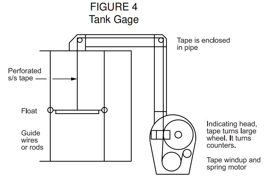
- Many types of level measuring devices are used in tanks, but ‘tank level’ measurement usually refers to the type of system shown in Figure 4.
- A large float in the tank, usually with guide rods or wires to keep the motion vertical, is attached to a perforated metal tape contained in and guided by piping. It passes through the top of the tank and extends to an indicating board, which may also be equipped with a signal transmitter for displaying the level at a remote location. Level alarm switches can also be installed in the measuring head.
- Pulleys change tape direction from vertical in the tank, to horizontal, to vertical again if required. For tanks at pressures of up to a few inches of water, a sealing liquid may be put into a pocket in the tape
piping. The sealing liquid has to be compatible with the stored fluid. Higher pressures, to 50 psig, may involve pressurizing the gage head. - The tape is exposed to the vapor space in the tank and then passes over pulleys and out of the tank. With time, material carried by the tape can accumulate around the pulleys and interfere with free motion.
- Precision of the tank level gage is approximately 1 mm ( 1/16 in) at any point in the operating range, unlike most process instrumentation which typically has a precision of 0.5 percent of its operating range.
- Gage heads can be mounted at ground level, for convenience, and to reduce the need to climb the tank. They can also be installed on top of the tank, reducing the length of the tape and eliminating some of the pulleys.
- In some applications, the directly operated float gage has been replaced by the Servo Tank Gage. This uses a motor to supplement the force generated by the float. The force on the float is detected and controls the motor. Frictional losses in the tape and pulleys are mostly overcome by the motor, thus improving accuracy. Reliability may also be improved if friction is the primary reason for failure in a specific installation, but the added complexity partly offsets this.
Solids Level Gage
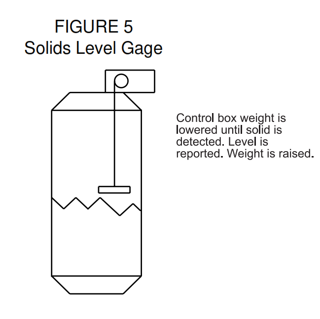
- Solids level can be measured by lowering a float into a tank until the surface of the solid is detected. See Figure 5. The float is usually lifted back up to a storage position at the top of the tank. The
measurement may be ‘on demand’, requiring operation of the start button for each measurement, or it may be semi-continuous, with the raising and lowering cycles continuously following each other. With this method, readings are updated every few minutes. - Accurate readings are not usually possible during filling. The float should not be installed directly below the filling connection, and should be lifted to the top during filling unless the measured solid cannot harm the float.
- An independent level switch is recommended for alarms or interlocks.
Precautions
- Changes in calibration can occur due to changes in fluid density, caused by chemical composition, pressure or temperature variations.
- Additional errors may be developed if the float has to provide appreciable energy to operate a switch, or indicating or transmitting mechanism.
- Hollow floats can develop leaks and fail.
- For all instruments, both the normal range of operating conditions, and the possible extremes of pressure, temperature and variations in chemical composition which could destroy the exposed parts shall be defined.
- Float type level sensors require nozzles or ports in the vessel to provide access. The way that fluid flows into, out of, and within the vessel shall be considered, as any resulting fluid currents could damage the sensor. Stilling wells or baffles may be used for protection, although the side effects of such structures have to be considered. Baffles or stilling wells which are too restrictive will cause the measurement to lag behind the actual level, and small openings will eventually plug up.
- If a hazardous fluid is involved, or if overflow will cause a hazard, or if overfilling will damage the tank, an independent level sensor and alarm switch shall be provided as a back up.
- For very hazardous fluids, or for very large vessels, further redundancy is justified. Additional tank nozzles may also be provided, to accommodate other devices in the future.
- For flammable fluids and electrically classified areas, all possible hazards and code requirements shall be considered. The hazards of the possible introduction of harmful vapors into a conduit system shall be considered, and the required seals and vents provided.
- When gaging solids levels with a moving float, the effects of any other mechanical devices in the vessel shall be considered. Mixers, vibrators, and other equipment could interfere with proper operation of, or cause damage to the float, so it may be necessary to prevent simultaneous operation.
Float Type Level Advantages
- Even with large changes in liquid density, the immersion of a large diameter float will change very little, thus density has little effect on accuracy.
- Float systems are simple and easily understood.
- Even if the primary requirement is the transmitted signal, local indicators can continue to operate, even on loss of power.
Float Type Level Disadvantages
- Float systems are difficult to maintain.
- Wire on tape breaks because of corrosion and chemical effect.
- Stilling columns are required when float systems are used to measure level in turbulence.
This article was guide for use of float type level sensors in process plants. Main keywords for this article are Float Type Level Measurement. Float Switches. Level Indicator. Tank Gage Level. Solids Level Gage.Float Type Level Advantages.Float Type Level Disadvantages.
