This article is about Foundation Fieldbus Technology and focusing to the engineers, technicians and supervisors. You will find lot of documents related to this article. Just navigate our website www.paktechpoint.com and find more articles. Please! Do not forget to subscribe our You tube channel also. Thanks in Advance.
PLEASE SUBSCRIBE OUR PAKTECHPOINT YOUTUBE CHANNEL
Foundation Fieldbus Technology
All devices on a bus must use the same options for media, connection and transmission rate.
However, bus or non-bus powered devices may be mixed, as well as intrinsically safe or non-intrinsically safe ones.
Fieldbus Physical Layer
Closed loop control with performance like a 4-20 mA system, and variable speed drives require high data transmission speed. Since higher speed means higher power consumption, it then clashes with the need for intrinsic safety in some applications. Therefore one moderately high communication speed was selected, and other faster non-intrinsically safe options where also made available, catering to all applications. The system was designed to have a minimum of communication overhead to meet control requirements even with the low speed option.
There are several combinations for the physical layer, each with their relative merits. All devices on a bus must use the same options for media, connection and transmission rate. However, bus or non-bus powered devices may be mixed, as well as intrinsically safe or non-intrinsically safe ones.Physical media options:
There are several combinations for the physical layer, each with their relative merits. All devices on a bus must use the same options for media, connection and transmission rate. However, bus or non-bus powered devices may be mixed, as well as intrinsically safe or non-intrinsically safe ones.Physical media options:
•Wire
•Fiber optics (pending)
•Radio (pending)
Transmission rate options:
•31.25 kbit/s
•1 Mbit/s
•2.5 Mbit/s
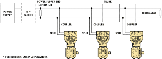
Fieldbus Topology – BUS
The wire media uses electrical signals on a normal twisted pair wire, and is already approved as an IEC/ISA standard
The wire media uses electrical signals on a normal twisted pair wire, and is already approved as an IEC/ISA
standard since 1992.The maximum distance allowed between two devices on wire media depends on the transmission rate selected.
standard since 1992.The maximum distance allowed between two devices on wire media depends on the transmission rate selected.
•31.25 kbit/s: 1,900 m
•1 Mbit/s (voltage mode): 750m
•1 Mbit/s (current mode): 750m
•2.5 Mbit/s: 500m
The device must isolate the communication hardware, Media Attachment Unit (MAU), from ground to avoid electrical ground loops when devices are multidropped.
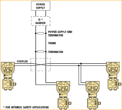
Bus topology , tree topology and point-to-point topologies are supported. Tree topology is only supported by the low speed version. The bus has a trunk cable with two terminators. The devices are connected to the trunk via spurs. The spurs may be integrated in the device giving zero spur length. A spur may connect more than one device, depending on the length. Active couplers may be used to extend spur length.
Active repeaters may be used to extend the trunk length.
Active repeaters may be used to extend the trunk length.
Fieldbus Topology – TREE
The wire media uses electrical signals on a normal twisted pair wire, and is already approved as an IEC/ISA standard
Signal Modulation
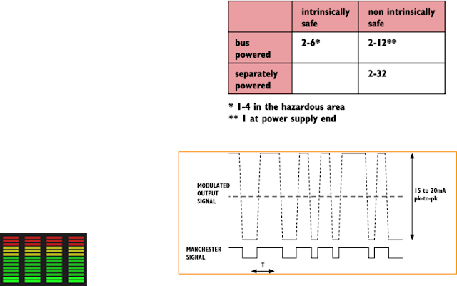
A device transmits by modulating current in the network according to the Manchester encoded signal. Receiving devices sense the voltage drop generated over the two terminators as the current is modulated.
The terminators are designed to have an impedance of 100 each around the transmission frequency. A device transmits by modulating current in the network according to the Manchester encoded signal. Receiving devices sense the voltage
drop generated over the two terminators as the current is modulated. The modulated current is 15 to 20 mA peak-to-peak for the low speed version, with a receiver sensitivity of 150 mV.
drop generated over the two terminators as the current is modulated. The modulated current is 15 to 20 mA peak-to-peak for the low speed version, with a receiver sensitivity of 150 mV.
The lowest speed wire media option, 31.25 kbit/s, is the most versatile and expected to be the most widely used type. It offers versions for intrinsic safety and device powering by bus. The number of devices is limited by this choice.
•Intrinsically safe / non-intrinsically safe
•Bus powered / Separately powered
The typical number of devices is indicated in table, the actual number varies from device type to device type.
In intrinsically safe systems, the safety barrier should be placed between the power supply and the power supply
end terminator.Devices may be powered by the bus, only requiring two wires for supply and communication. A single power supply, common to all devices, is connected to the network at either end of the trunk. The voltage may be in the range 9-32
VDC. The impedance of the power supply must be a minimum of 3 k around the transmission frequency in order
not to short circuit the communication signal. A Manchester coded signal has a duty-cycle of exactly 50% and can be seen as a AC signal. The DC power consumption (power drawn) of a device is therefore constant.
Fieldbus Physical Layer for H1 Fieldbus
The H1 Fieldbus can be used for control applications such as temperature, level and flow control. Devices can be powered directly from the Fieldbus and operate on wiring that was previously used for 4-20 mA devices
The H1 fieldbus can be used for control applications such as temperature, level and flow control. Devices can be powered directly from the fieldbus and operate on wiring that was previously used for 4-20 mA devices. The H1 fieldbus can also support intrinsically safe (I.S.) fieldbuses with bus powered devices. An I.S. barrier is placed between the power supply in the safe area and the I.S. device in the hazardous area.
H1 Fieldbus Signaling
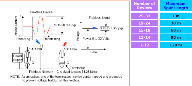
The transmitting device delivers ±10 mA at 31.25 kbit/s into a 50 ohm equivalent load terminator to create a 1.0 volt peak-to-peak voltage modulated on top of the direct current (DC) supply voltage. The DC supply voltage can range from 9 to 32 VDC. However, for I.S. applications, the allowed power supply voltage depends on the barrier rating.
H1 Fieldbus Wiring
The H1 fieldbus allows stubs or “spurs” as shown. The length of the fieldbus is determined by the communication
rate, cable type, wire size, bus power option, and I.S. option. The main run cannot exceed a total length of 1900 m (6,232 ft)
with shielded twisted pair cable. The cable length is determined by adding together the length of the trunk cable and all of the spur lengths. As shown in Figure , terminators are located at each end of the main trunk cable. If you have a choice about the length of a spur, shorter is better. The total spur length is limited according to the number of spurs and the number of devicesper spur.
Please read also: https://paktechpoint.com/over-speed-protection-in-compressor/


