Main keywords for this article are Gas Positive Displacement Flowmeters Design Requirement, Working Principle Rotary Vane Meter, Working Principle Lobed Impeller Meter, Working Principle Four Chamber Bellows Meter, Working Principle Wet Test Meter, Positive Displacement Flowmeters Advantages, Positive Displacement Flowmeters Disadvantages, Positive Displacement Flowmeters Precautions.
Gas Positive Displacement Flowmeters Design Requirement
We have different types of Gas Positive Displacement Flowmeters and each one will be discussed with images clearly.
Working Principle Rotary Vane Meter
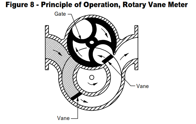
Rotating Vane (also known as rotating piston). Figure 8 illustrates the principle of operation of a typical rotating vane meter for gas service. The meter may contain two or four capillary sealed
vanes and a gate. The gate is gear-synchronized with the vanes, permitting them to pass from the outlet port to the inlet port and preventing incoming gas from bypassing the measuring chamber.
- Materials of Construction
a. Housings: Cast iron ductile iron, steel, aluminum
b. Internals: “Teflon®”, aluminum - Sizes, Capacities, Accuracy
a. Connections: 2 inches to 4 inches
b. Capacities: Continuous flow, 150 to 11,000 scfh at 4-oz water pressure
c. Accuracy: + ½ to 1 percent error, 10:1 to 25:1 ranges - Pressure-Temperature Ratings
a. Maximum Pressure: 125 psig
b. Temperature Range: -40 to 70 °C (-40 to 155 °F)
Working Principle Lobed Impeller Meter
- Lobed Impeller (also known as Rotary, Bilobal, Roots)
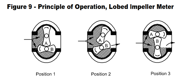
The metering elements are two gear-synchronized figure-eight rotors rotating within a cylindrical measuring chamber, Figure 9. The operating principle is the same as that for the oval gear meter as described in 4.6. The basic differences between the two meters are the shape of the rotors and the fact that the figure-eight rotors are smooth, relying on capillary seals between them to prevent the entering gas from bypassing the measuring chamber.
Capillary seals between the rotors and the walls of the measuring chambers trap precise quantities of gas in the chambers.
- Materials of Construction
a. Housings: Cast iron, aluminum
b. Rotors: Cast iron, aluminum - Sizes, capacities, accuracy
a. Connections: 2 inches to 10 inches
b. Capacities: Continuous flow, 150 to 102,000 scfh at 14.73 psig and 15 °C (60 °F)
c. Accuracy: + ½ to 1 percent error, 10:1 to 20:1 ranges - Pressure-Temperature Ratings
a. Maximum Pressure: 125 to 1,440 psig
b. Temperature Range: -40 to 120 °C (-40 to 250 °F)
Working Principle Four Chamber Bellows Meter
Bellows (also known as Dry Positive-Displacement, Four- Or Three-Chamber Bellows, Or Diaphragm).
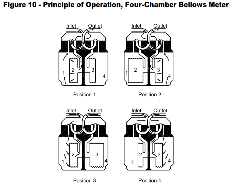
The principal elements of these meters are the flexible gastight elastomeric bellows of the measuring chambers, valves for controlling and directing the gas flow in filling and emptying the measuring compartments, appropriate linkages to keep the diaphragm and valves in synchronism, and a counting register. To obtain continuous flow and power for operating the register, it is necessary to have three or more measuring chambers with two or more movable walls which are sealed with an elastomericcoated fabric impervious to gas.
Figure 10 illustrates the operation of a four-chamber meter through one complete cycle. In Position 1, Chamber 1 is emptying, 2 is filling, 3 is empty, and 4 has just filled. In Position 2, Chamber 1 now is empty, 2 is full, 3 is filling, and 4 is emptying. In Position 3, Chamber 1 is filling, 2 is emptying, 3 is filled, and 4 has emptied. In Position 4, Chamber 1 is filled, 2 is empty, 3 is emptying, and 4 is filling. Meters can be supplied for special services up to 350 psig for oxygen, hydrogen, helium argon, acetylene (15 psig), Also, small portable dry test meters for field or laboratory testing of gas unsaturated with water are available.
- Materials of Construction
a. Housings: Cast iron, ductile iron, aluminum
b. Internals: Combination of aluminum, steel, tin, and elastomeric coated fabric - Sizes, Capacities, Accuracy
a. Connections: ½ inch to 4 inches (portable meters: ½ inch to 1-1/4 inches)
b. Capacities: Continuous flow, 4 to 5,000 scfh at ½ inch of water differential and 35 to 1,000 scfh at 2 inches of water differential (portable meters: 5 to 325 scfh at ½ inch of water differential)
c. Accuracy: + ½ percent error, 20:1 range - Pressure-Temperature Ratings
a. Maximum Pressure: 5 to 1,000 psig (portable meters: 5 to 10 psig)
b. Temperature Range: -30 to 60 °C (-20 to 140 °F)
Working Principle Wet Test Meter
Wet Test (also known as Rotating Drum).
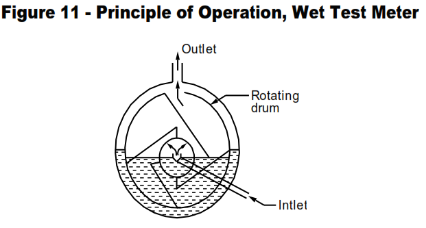
The wet test meter is suitable for field and laboratory measurement of gases at low flow rates and is available in bench and portable models. The meter contains a hollow stainless steel drum with several compartments, Figure 11. Passage of gas through the meter causes the drum to rotate. When the case is filled with liquid to a predetermined level, each compartment is filled and emptied successively. Since the volume of each compartment is known, the record of rotation of the drum is a measure of the quantity of gas passed.
- Materials of Construction
a. Housings: Stainless steel, epoxy-lined aluminum
b. Internals: Stainless steel - Sizes, Capacities, Accuracy
a. Connections: Hose and 3/8 inch to 1-1/4 inches
b. Capacities: Continuous flow, 0.24 to 480 scfh at 0.3 inch of water differential (portable meters: 0.24 to 16 scfh at 0.3 inch of water differential)
c. Accuracy: + ¼ percent error, 3:1 range and + ½ percent error, 10:1 range - Pressure-Temperature Ratings
a. Maximum Pressure: 12 to 14 inches of water (portable meters: 30 psig)
b. Temperature Range: -5 to 50 °C (25 to 125 °F)
Positive Displacement Flowmeters Advantages
- If adequately maintained, Positive Displacement Flowmeters are accurate with well defined tolerances (less than 2 percent error) and with excellent repeatability over flow ranges normally 10:1 to 20:1.
- Above viscosities of several centipoises, liquid meters are available which retain accuracy over a wide range of viscosities (oscillating piston, reciprocating piston, and rotating vane).
- Pressure drops are low, generally 2 to 6 psig for low viscosity liquids (the reciprocating piston meter is an exception), and Iess than 3 inches of water for gas meters operating at pressures up to 35 psig (10 inches and Iess at 150 psig).
- These meters are particularly suited for measuring fluids for accounting purposes, blending, and batching operations.
- Portable transfer provers are available for proving (calibrating) gas meters in the field.
- Certain type of Positive Displacement Flowmeters are the most satisfactory means for measuring pulsating flow since the volume of flow is measured directly, not inferred as in rate meters. Refer to vendor information for specific application.
- Liquid meters are unaffected by turbulence or other abnormal flow distribution.
- Inlet piping configuration is not critical for liquid meters.
Positive Displacement Flowmeters Disadvantages
- A change of state in the fluid being metered will introduce errors.
- Relatively large meter bodies are required for a given flow rate as compared to rate meters.
- Because of the small clearance required to achieve accuracy, the meters are susceptible to damage by foreign and abrasive material.
- Cost and size limit applications of Positive Displacement Flowmeters as compared to rate meters.
- Since the meter body contains both the primary and secondary elements, when a change in the size or capacity of a pipeline requires changing the meter, the entire meter must be replaced.
- The presence of entrained gas and vapor in liquids will result in measurement errors.
- To avoid binding because of the small clearances, meters must be installed carefully on firm, level foundations and must not be stressed by external loads due to misaligned or expanding and contracting piping.
- Meter capacities cannot be altered.
Positive Displacement Flowmeters Precautions
- Because of the small clearances, rated operating temperatures should not be exceeded without the manufacturer’s approval. Where the operating temperature is close to the maximum rating, the meter should be brought up to temperature slowly to permit the case to warm up so that the internals are not damaged by binding.
- Liquids must be free of entrained gas or vapor because these will be registered as liquid. Installation of an automatic air release chamber upstream of the meter may be required. Also, the meter should not be installed at a high point in the l ine where gas or vapors may accumulate.
- Because of the small clearances, strainers should be installed to prevent damage or excessive wear if fluids contain dirt. Generally, a 100-mesh screen is adequate for small meters (1-inch connections and smaller), decreasing to 40-mesh for 4-inch and larger meters.
- Meters should be calibrated with liquids having physical characteristics similar to those of the liquids to be metered. For maximum accuracy, meters should be calibrated at pressures and temperatures comparable to the service conditions to eliminate errors due to dimensional changes.
- Recommended flow rate ranges should not be exceeded if the rated accuracy is to be maintained. Errors increase rapidly below rated minimum flow rates because slip becomes an increasingly significant factor. Flow surges may cause permanent damage. Care must be exercised when putting meters in service to avoid overspeeding due to flushing, blowing, or steaming-out lines.
- Fluctuating flow rates can cause serious errors in wet test meters due to surging of the seal liquid. Accuracy is highly dependent upon maintaining the seal liquid at the proper level.
- If temperatures can rise where meters are isolated by upstream and downstream valves, relief valves should be installed to prevent fracture of the cases or damage to the internals due to overpressure.
- To avoid breaking or distorting pistons and vanes, liquid meters should not be subjected to water hammer.
- Pressure on gas meters should be applied and released slowly.
- If pipelines are to be steamed, install meters in a bypass line.
Check out this article Part I.
Positive Displacement Flowmeters Design Requirement in Process Industry
Check out this article Part II.
Liquid Positive Displacement Flowmeters Design Requirements
Check out this article Part III.
Main keywords for this article are Gas Positive Displacement Flowmeters Design Requirement, Working Principle Rotary Vane Meter, Working Principle Lobed Impeller Meter, Working Principle Four Chamber Bellows Meter, Working Principle Wet Test Meter, Positive Displacement Flowmeters Advantages, Positive Displacement Flowmeters Disadvantages, Positive Displacement Flowmeters Precautions.


