This article is about GSM KPIs Analyszing and Troubleshooting andfocusing to the engineers, technicians and supervisors. You will find lot of documents related to this article. Just navigate our website www.paktechpoint.com and find more articles. Please! Do not forget to subscribe our Youtube channel also. Thanks
GSM KPIs Analyszing and Troubleshooting PART-2 DCR
High DCR:
DCR is purely dependent on TCH drops and call volume.
AFFECTING FACTORS of Dropped call rate
The reasons for TCH drops are segregated majorly into following types of drops:
– Radio Drops
– HO Drops
– ABIS Drops
– BTS Drops
– LAPD Drops
– User-Action Drops
– A-interface Drops
– Transcoder Drops
RECTIFICATION PROCEDURES:
– Radio Drops
Radio drops encompass RF drops (RLT timeout), which could be due to following reasons:
Poor signal level (Rx-Level) in dedicated (call) mode. This could be due to coverage holes created by aggressive down tilting, illogical orientation, or inadequate antenna height for desired coverage area. Obstructions due to terrain/building structure could also be reasons for low Rx-level. Site design needs to be revised to counter issues arising due to such obstructions.
Since common BCCH configuration is being used in Telenor Pakistan, Rx-Level might be hit on DCS layer as well. Make sure that the antennae, both DCS and GSM, are correspondingly tilted so that their coverage footprint is similar to that of 900.
–
If Power Control is used, make sure that level thresholds are optimized well to avoid aggressive power reduction that might lead to poor Rx-level and dropped calls.
If Power Control is used, make sure that level thresholds are optimized well to avoid aggressive power reduction that might lead to poor Rx-level and dropped calls.
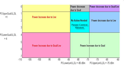
Power Control is used to reduce interference by decreasing power of BTS as well as MS. The power reduction adjustment is based on Rx-Level and Rx-Qual thresholds. Following snapshot gives a bird’s eye view of the concept of Power Control:
Concept of Power Control
User will receive poor signal level from neighboring cells if its logical server has outage; leading to increased probability of call drops.
Increased call drops might be experienced due to poor Signal Quality (Rx-Qual). It is dependent on Bit Error Rate (BER); higher the BER, worse will be the Rx-Qual. It is mainly due to poor C/I.
– Pro-interference frequency plan leads to very low C/I; RF Engineers should revise the frequency plan.
– High VSWR between BTS cabinet and antenna (feeder cable problem, combiner issues etc.) could also lead to poor quality; issue to be raised to O&M for rectification. A faulty piece of equipment, TRX specially, may also result in poor Rx-Qual, and the issue needs to be raised to O&M.
Overshooting cells might interfere as well; ensuring proper coverage of cells (through tilts, orientation, and height adjustments) is one of the major responsibilities of an RF Optimizer.
– Rx-Qual is heavily dependent on Handover Control and adjacency parameter. The HO parameters need to be optimized well so that call is handed over to better cell before quality gets hit (handover on the basis of relatively better signal level).
Please read also: Power Control in GSM for RF Optimization
Please read also: 3G KPI Improvement Report 2nd
Please read also: 3G / WCDMA OPTIMIZATION ARTICLES
HO Drops
Handover Drops are of significant importance from RF Optimization point of view as RF Engineers define the neighbor relations for performing handovers. Handover drops need quite rigorous analysis as there are many factors affecting these drops. HO drops can be majorly analyzed on these bases:
– Bad Neighbor Plan
– Poor RF Environment
-Database Discrepancies
– Non-standardized values of Adjacency and HO control parameters
– Wrong/Incomplete External LAC Plan
Before these points are discussed in detail, it is imperative to be clear on the concept of source and target cells. A source cell is the one on which MS is currently camped. The call can be handed over to only those cells that are defined as neighbors (target cells) of source cell. The BSC has an “Adjacency Table” for all cells containing the target cell information. This table contains only that information for target cells which is provided by RF engineer when having adjacencies/neighbors defined i.e. the target cell information at the source cell could be different from the actual information of target cell. For example, Source cell “A” has a neighbor “X”. Suppose that cell X is actually allotted LAC: 100. Now if cell A has wrong LAC information with it for cell “X”, it will lead to handover failures, and may also lead to HO drops as MS might not be able to camp back onto the source cell TCH.
Bad Neighbor Plan
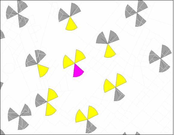
RF Optimizer has to ensure that neighbor plan contains all logical relations (geographically first tier cells at least). An example of a precise neighbor plan is:
An example of Neighbor Plan
Note: Refer to Neighbor Optimization section in Progressive Optimization
Poor RF Environment– Apart from ensuring geographically logical neighbor plan, the RF environment needs to be clean; for making successful handover attempts, the interference has to be minimal.
Database Discrepancies– Since database changes for handover parameters are quite frequent, database needs to be periodically checked for discrepancies. There might be some discrepancies between adjacency database and actual target cell information. Such discrepancies could include:
– BCCH
– BSIC (NCC/BCC)
– LAC
– Cell ID
All such adjacency discrepancies need to be removed on high priority by RF engineer.
Non-Standardized values of Adjacency and HO Control Parameters–
An RF Optimizer should know in detail the Adjacency and HO Control parameter set. Adjacency parameters majorly include:
i.) BCCH, BSIC, LAC, Cell ID information for target cell
ii.) Rx-Level margins for making handover attempts on the basis of relative signal strength (Power Budget Handover Margins)
iii.) Thresholds for minimum acceptable Rx-level of target cell to qualify for making handovers.
Handover Control (HOC) parameters
HOC majorly include:
i.) Thresholds and averaging mechanisms for making Quality based handovers (Both Uplink and
Downlink)
Downlink)
ii.) Thresholds and averaging mechanisms for making Level based handovers (Both Uplink and
Downlink)
Downlink)
iii.) Non-BCCH Layer Access and Exit Thresholds & averaging mechanisms (thresholds/averaging mechanisms for access to and exit from DCS layer for Telenor Pakistan Network)
An RF Optimizer has to ensure that all cells have standardized values of these parameters.
Wrong/Incomplete External LAC Plan– The External LACs are defined in MSCs so that inter-MSC handovers can be done. LACs have to unique for MSCs in the Network. If the External LAC definitions are not correct or are incomplete in an MSC, then handovers will fail between MSCs; thus increasing the probability of HO Drops. External LAC plans are provided by RF engineer, and are implemented in MSCs by NSS
Department.
Department.
Note: HO failures not only cause HO Drops, but can also be responsible for Radio (RF) drops: a call, if not handed over, will be dragged on the source cell while level will fade with increasing distance from BTS; the call continuing in poor RF environment may ultimately be dropped.
– ABIS Drops
ABIS failures/drops are due to issues on ABIS interface. Such cases need to be raised to O&M on Service
Desk.
Desk.
– BTS Drops:
BTS drops appear due to problem on the BTS, and have to be rectified by O&M. RF engineer to raise such issues via Service Desk.
– LAPD Drops:
LAPD drops appear if there is some problem on D-Channel link. These drops also appear when there is cell/site outage i.e. all calls, when outage appears, are dropped and pegged into LAPD failure. Such issues need to be raised to BSS O&M via Service Desk.
– User Action Drops:
User action drops appear when an engineer (user) locks the TRX/cell/site for some configuration changes.
– A-interface Drops:
A-interface drops appear due to issues on the interface between BSC and MSC. These issues also need to be raised via Service Desk.
– Transcoder Drops:
Transcoder drops appear due to problems on E1 terminating at Transcoder. These issues need to be raised to BSS O&M via Service Desk.
Statistical
Data for Troubleshooting High DCR:
DCR values for BH/DL can be seen from ‘Nokia Harmonized Stats’ tool for xNokia cells/BSCs, and from ‘StatMon’ tool for xSiemens cells/BSCs.
RF Drops, HO Drops, and Transcoder Drops are available in ‘Nokia Harmonized Stats’ tool for xNokia cells, and in ‘StatMon’ tool for xSiemens cells. ABIS Drops for xNokia Cells are available in ND Report: 163 (contains all the other drops mentioned above as well). StatMon has ABIS drops, LAPD Drops, BTS Drops
and A-interface Drops for xSiemens. User Action Drops are available for xNokia cells only.
and A-interface Drops for xSiemens. User Action Drops are available for xNokia cells only.
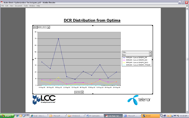
DCR Distribution from Optima
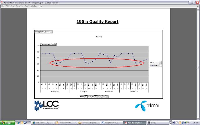
TRX Level Rx-Quality statistics are available for xNokia cells in ND Report: 196. Cell level Rx-Qual statistics are available from Optima, and are appended into ‘Nokia Optima Harmonized Stats’ tool. TRX level stats of Rx-Qual for xSiemens are extracted from Optima query and are appended into ‘StatMon’ tool.
196 Report for Quality
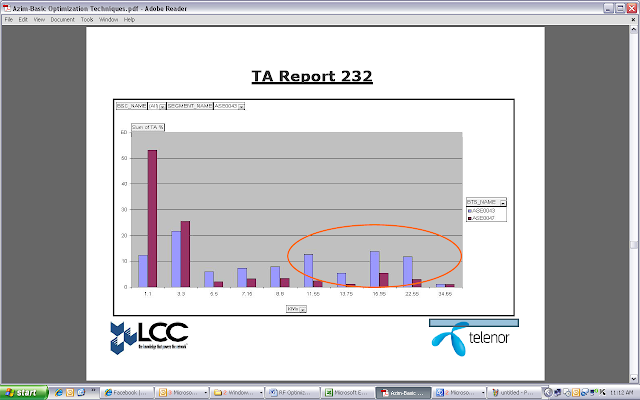
Use statistics for Timing Advance (TA, 1TA= 550m) as they give quite good indication of coverage foot print of the cell, hence, an indication of signal penetration in corresponding area. These stats can be extracted for xNokia cells from ND Report: 232, and by using Optima query (appended into ‘Nokia Optima Harmonized Stats’ tool) as well. For xSiemens cells, TA stats are extracted by using Optima query, and are appended into ‘StatMon’ Tool.
TA Report 232
There are eight TA ranges defined for xNokia and xSiemens cells separately, and the breakdown is as follows:
|
Nokia
|
Siemens
|
||
|
TA
|
Distance
|
TA
|
Distance
|
|
1
|
Up to 550 m
|
0
|
Up to 550 m
|
|
2
|
>= 550 m and up to 1.1 Km
|
1
|
>= 550 m and up to 1.1 Km
|
|
3
|
>= 1.1 Km and up to 1.65 Km
|
2
|
>= 1.1 Km and up to 1.65 Km
|
|
6
|
>= 1.65 Km and up to 3.3 Km
|
3
|
>= 1.65 Km and up to 2.2 Km
|
|
10
|
>= 3.3 Km and up to 5.5 Km
|
4
|
>= 2.2 Km and up to 4.4 Km
|
|
20
|
>= 5.5 Km and up to 11 Km
|
5
|
>= 4.4 Km and up to 8.8 Km
|
|
40
|
>= 11 Km and up to 22 Km
|
6
|
>= 8.8 Km and up to 17.6 Km
|
|
63
|
>= 22 Km and up to 35 Km
|
7
|
>= 17.6 Km
|
