To read about structure of CSI-RS, you must read below.
Why was CSI-RS introduced into NR?
How is CSI-RS classified and what are the functions of CSI-RS?
Basic Structure of CSI-RS.
Channel quality in NR depends on transmit power and the number of antenna ports used for transmission. CSI-RS facilitates channel sounding across multiple antenna ports, supporting configurations from 1 to 32 ports. Each antenna port corresponds to a distinct channel that requires evaluation.
To prevent conflicts, restrictions are placed on CSI-RS resource configurations concerning critical downlink physical channels and signals, such as:
- CORESET (Control-resource set) assigned to the UE.
- DMRS for PDSCH (Demodulation Reference Signals).
- SSB (Synchronization Signal Block).
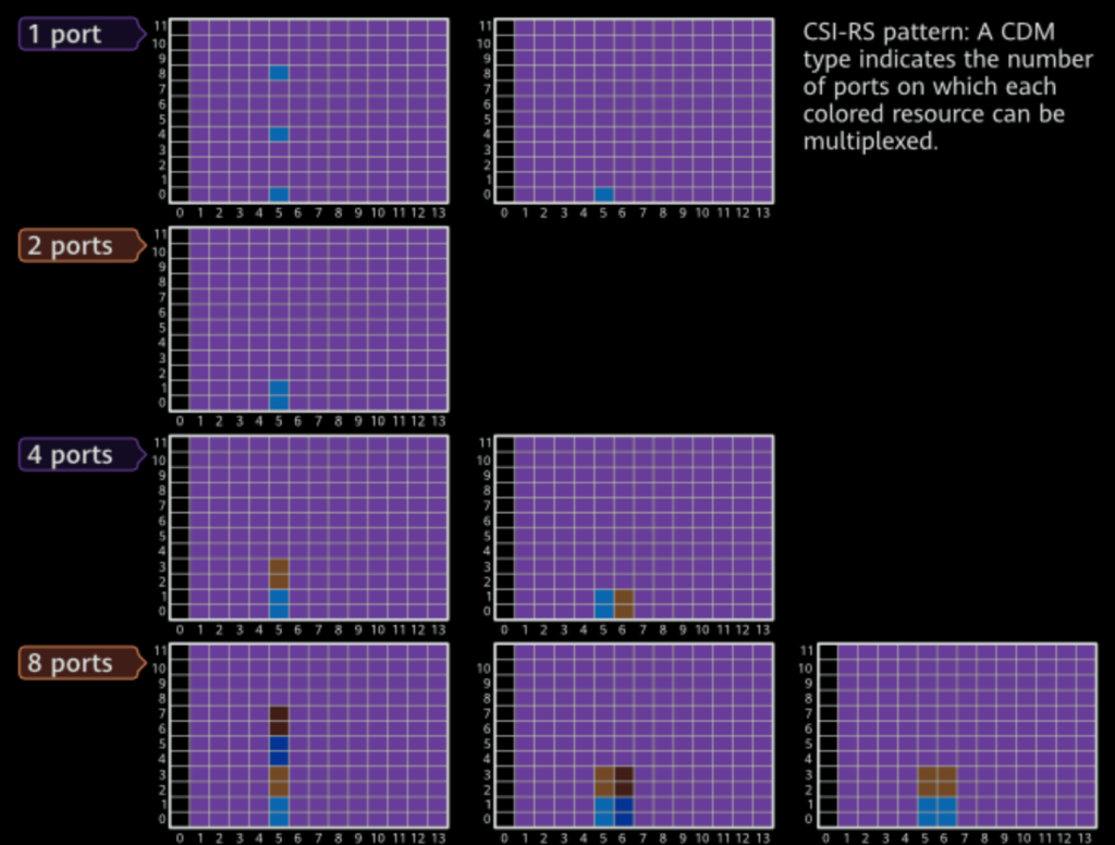
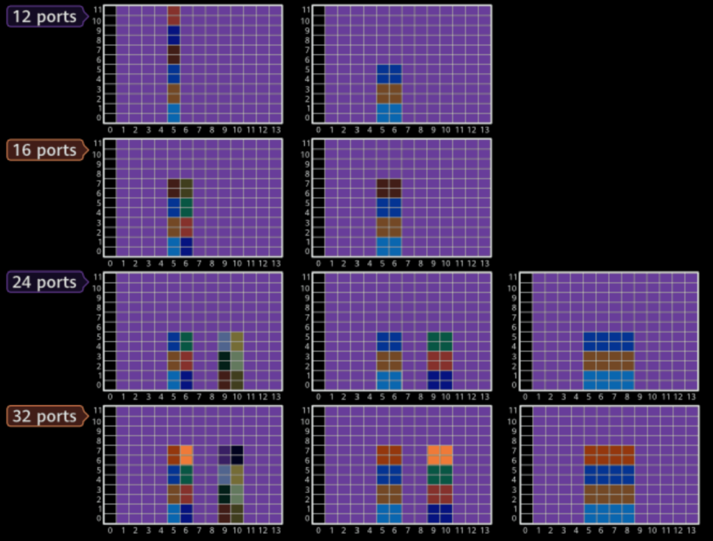
The CSI-RS transmitted over multiple antenna ports is realized by multiplexing mutually orthogonal signals on a group of resource elements (REs) using these methods:
- Code Division Multiplexing (CDM): Orthogonal codewords differentiate CSI-RS signals on the same REs across different ports.
- Frequency Division Multiplexing (FDM): Distinct frequency subcarriers are used within the same symbol across ports.
- Time Division Multiplexing (TDM): Different time symbols within the same slot separate CSI-RS signals for different ports.
These methods ensure effective multi-port channel sounding.
CSI-RS configurations that combine CDM, FDM, and TDM offer flexibility in mapping multiple antenna ports to time-frequency resources. The resource configuration includes:
- Time-Domain Symbols: CSI-RS can occupy 1–4 symbols, specified by higher-layer signaling.
- Time Position: Higher-layer parameters define the time slot.
- Frequency Position: Set via the CSI-RS-ResourceMapping parameter, enabling configurations in every RB or alternate RBs within the active BWP.
The patterns and configurations adapt based on the number of antenna ports and multiplexing techniques, ensuring efficient utilization of REs. For exact patterns, refer to 3GPP TS 38.211 V15.7.0.
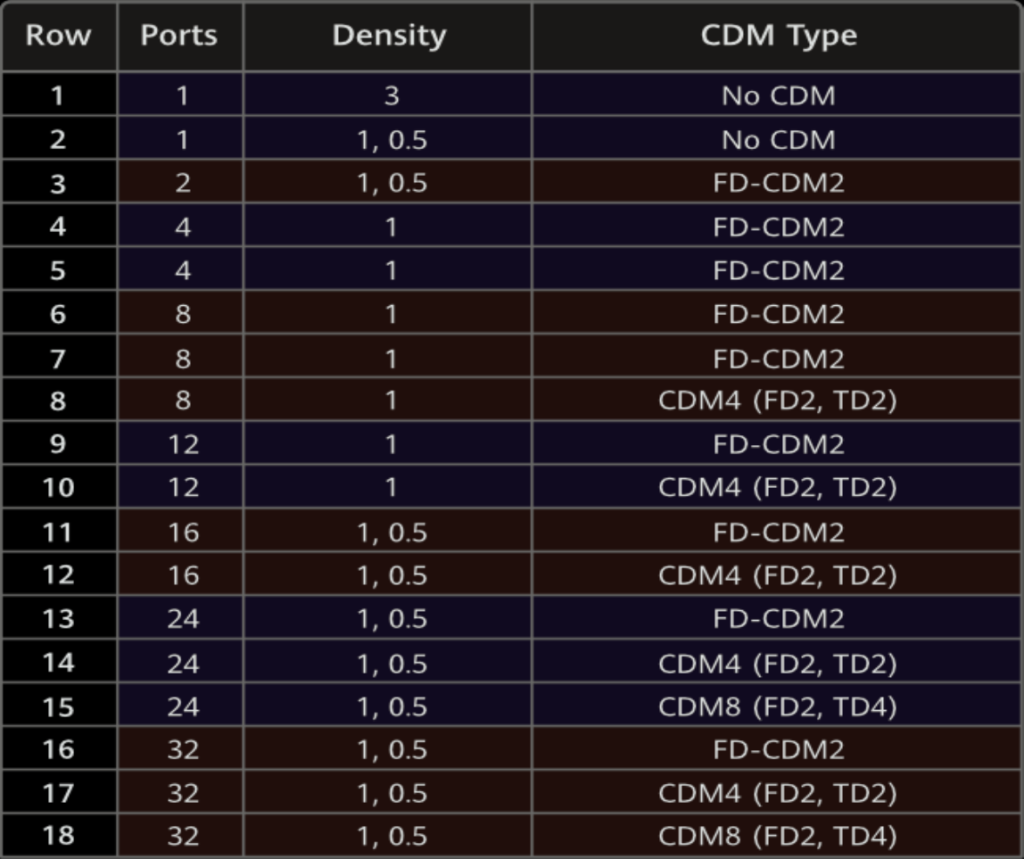
Below figure-1 shows CSI-RS pattern configuration.

Below figure-2 shows Examples of CSI-RS patterns.


In the frequency domain, the CSI-RS density determines how CSI-RS resources are distributed across a PRB:
- Density of 3: Three REs per PRB are used for transmitting CSI-RS on a single antenna port.
- Density of 1: CSI-RS occupies every PRB.
- Density of 0.5: CSI-RS is transmitted on alternating PRBs (odd or even). Configuration specifies which PRBs carry CSI-RS.
The bandwidth occupied by CSI-RS and its start position are defined by configuration parameters. This allows adaptable resource allocation based on requirements.
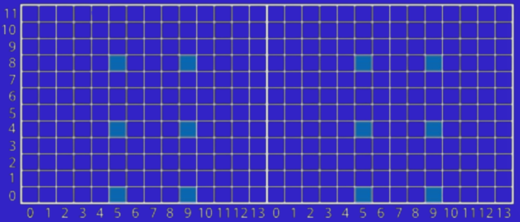
CSI-RS patterns are designed based on their specific applications in NR. CSI-RS for Channel Measurement (CM) uses a broad set of patterns defined in rows 2 to 18, accommodating multiple antenna ports and enhancing measurement accuracy for downlink conditions. For Beam Management (BM), the patterns are restricted to rows 2 and 3, with support for one or two antenna ports, making it suitable for RRM and beamforming tasks. Tracking Reference Signal (TRS) uses the pattern in row 1 and ensures precise time-frequency synchronization, essential for maintaining strong connectivity. TRS can be transmitted periodically or aperiodically, with timing controlled by higher-layer parameters or DCI.
Figure 3 shows TRS pattern of four single-port signals.

What are CSI-RS transmission schemes?
CSI-RSs can be transmitted to UEs periodically, aperiodically, or semi-persistently.
Periodic Transmission: In this mode, the gNodeB configures a fixed transmission interval (in terms of slots) and a symbol offset. This configuration is communicated to the UE, which then expects the CSI-RS to be transmitted at these regular intervals.
Aperiodic Transmission: The gNodeB dynamically signals the transmission of CSI-RS to UEs using DCI (Downlink Control Information) signaling. Each transmission is individually triggered by the gNodeB as needed.
Semi-persistent Transmission: Similar to periodic transmission, but the transmission is controlled by a MAC control element (CE). The CE specifies when the CSI-RS transmission should occur, with activation and deactivation triggered based on network requirements.
References.
- 3GPP TS 38.214, Physical layer procedures for data (Release 15).
- 3GPP TS 38.201, Physical layer; General description (Release 16).
- 3GPP TS 38.202, Services provided by the physical layer (Release 16).
- 3GPP TS 38.211, Physical channels and modulation (Release 15).