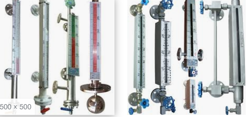
This article covers the general requirements for the selection and installation of level gauges. Main keywords for this article are Level Gauge Design Requirement. Special Point for Level Gauge Design. Instrument Installation.
Level Gauge Design Requirement in Process Industry
- Level gauges shall be of sufficient length to provide complete coverage of the range of the associated level instruments.
- Separate valving shall be provided for the level instrument and its associated level gauge. The use of a bridle assembly to reduce the number of vessel connections is acceptable.
- Level gauge shall be hydrotested to 1.5 times the process design pressure by the manufacturer prior to shipment. The manufacturer shall include the hydrotest documentation with shipment.
- Magnetic type level gauges shall be considered for:
a. Cryogenic services
b. Fluids that attack glass (e.g., strong acids, alkalies, boiler feed water)
c. Light ends services
d. Toxic services
e. Pressures above 3450 kPa (500 psi) special consideration must be given to the design of float for high pressure service. - Level Gauges process connections shall be in accordance with Instrument Installation Details.
Special Point for Level Gauge Design
- Reflex type gauge glass columns shall have the minimum pressure rating of 6900 kPa (1000 psig) at 315 °C (600 °F).
- A gauge glass unit length of approximately 300 mm (12.5 in) visible length shall be used. No more than five units may be used in one column. When two or more columns are required to cover a longer range, the visible portion of the gauge glasses shall overlap at least 25 mm (1 in).
- Above 205 °C (400 °F) operating fluid temperature, a single gauge glass column shall not contain more than three units nor exceed 1200 mm (48 in) between gauge glass column connections.
- Armored type gauge glasses shall be used. Tubular type is not permitted.
- Frost shields shall be used if specified operating temperature is below 0°.
- The gauge glass unit and cover plate shall be made of material suitable for the process conditions and vessel specifications.
- Lighting shall not be provided on thru-vision gauge glass columns, unless specified by Company.
- Where gauge glasses are specified for use in non-fouling processes and where the service conditions include any of the following then the gauge glass column or associated piping shall include a ball (excess flow) type check valve at each process connection. The design shall permit the commissioning of the gauge glass column without the need for external bypass piping.
a. Light ends service
b. Toxic services
c. Pressure above 3450 kPa (500 psi)
d. Temperature above the auto-ignition point. - Integral gauge glasses are allowed only on equipment that can be taken out of service without impacting unit operations.
- Gauge glass column installations for three-fluid systems are special. The preferred method is to use dual two-fluid installations. If a single three-fluid system is used, balance lines are required. A balance line shall be located where it is always covered with the middle fluid. More than one balance line shall be used if necessary to meet this condition.
Instrument Installation
- Level gauges shall be installed in accordance with Click Here requirements.
- Gage assemblies shall be end or side connected with the size of connections established by company.
- For temperatures below 177 °C (350 °F), a maximum of five (5) sections per assembly shall be used; for temperatures above 177 °C (350 °F), a maximum of four (4) sections per assembly shall be used.
- The gage glass shall cover preferably the full usable range, provided by process design and as a minimum cover the full range of the level transmitter, controller or alarms which may be installed on the same vessel.
- Nozzles shall be located on the vertical center line. Where level range is greater than allowable gage length, use additional nozzles or external stand pipe. Overlap nozzles sufficiently to obtain a continuous view of the liquid level.
- Where interface zones are present, use a separate pair of nozzles for each gage assembly. The bottom glass shall be transparent type with illuminator.
- Gage valves shall consist of Jerguson #675 or Penberthy #425 offset type with ¾” (20 mm) male NPT spherical union “tank” connections and ¾” (20 mm) NPT union gage connections.
- The ¾” (20 mm) male NPT union tail piece shall be connected to an appropriately rated ¾” (20 mm) threaded reducing flange bolted directly to the vessel block valve.
- A spool piece shall be added between the gage valve and primary block valve, if additional clearance from the vessel or other equipment is required.
- Piping and fittings shall conform to primary piping specifications and shall be socket or butt welded construction up to the gage block valve, except as illustrated.
- Orient connections and rotate gage to obtain best viewing, if the gage cannot be read or the valves operated from grade or platform(s), a ladder shall be furnished in a suitable location for level observation and valve operation. Ladder braces shall be positioned to avoid interference with the gage glasses.
- In steam service over 1034 kPa (150 psi), transparent gages with mica shields shall be used.
