Main keywords for this article are Liquid Positive Displacement Flowmeters Design Requirements, Working Principle Nutating Disk Meter, Working Principle Oscillating Piston Meter, Working Principle Sliding Vane Meter , Working Priciple Rotating Vane Meter, Working Principle Lobed Impeller Meter, Working Principle Oval Gear Meter, Working Principle Reciprocating Piston Meter.
Working Principle Nutating Disk Meter (also known as a Wobble Plate, or Disk)
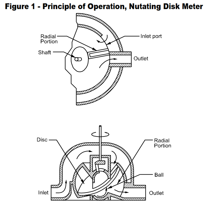
See Figure 1. Because of the simplicity of its construction, this type of meter can be produced very economically. Partly for this reason, and also because it will maintain a satisfactory degree of accuracy over a long period of time, it is the most widely used meter. The movable element is the disk mounted on a central ball, from the top of which a shaft extends that is perpendicular to the disk. This shaft is held in an inclined position so the disk is in contact with the chamber bottom on one side of the ball and in contact with the top on the other side of the ball. The disk is prevented from rotating about its own axis by a radial partition which also separates the outlet from the inlet. Liquid enters the measuring chamber alternately above and below the disk and passes around the chamber to the outlet port. For each cycle, the mete displaces a volume equal to the volume of the metering chamber minus the volume of the disk assembly. The top of the shaft moves in a circular path, operating the secondary element.
- Materials of Construction
a. Housings: Cast iron, steel, bronze, Ni-Resist, stainless steel
b. Disks: “Teflon ®,” Kel-F, carbon, hard rubber, aluminum, bronze - Sizes, Capacities, Accuracy
a. Connections: ½ inch to 6 inches
b. Capacities: Intermittent flow, 1 to 1,000 gpm, low viscosity lubricating liquids
c. Accuracy: + 1 to 1-1/2 percent error, 10:1 range.
d. Repeatability: 0.5 percent - Pressure-Temperature Ratings (standard meters)
a. Maximum Pressure: Normally 150 psig all sizes. Meters 4 inches (500 gpm maximum) and smaller are available for pressures from 600 to 5,000 psig
b. Temperature Range: -40 to 120 °C (-40 to 250 °F) depending upon piston material
Working Principle Oscillating Piston Meter (also known as Rotary or Ring Piston)
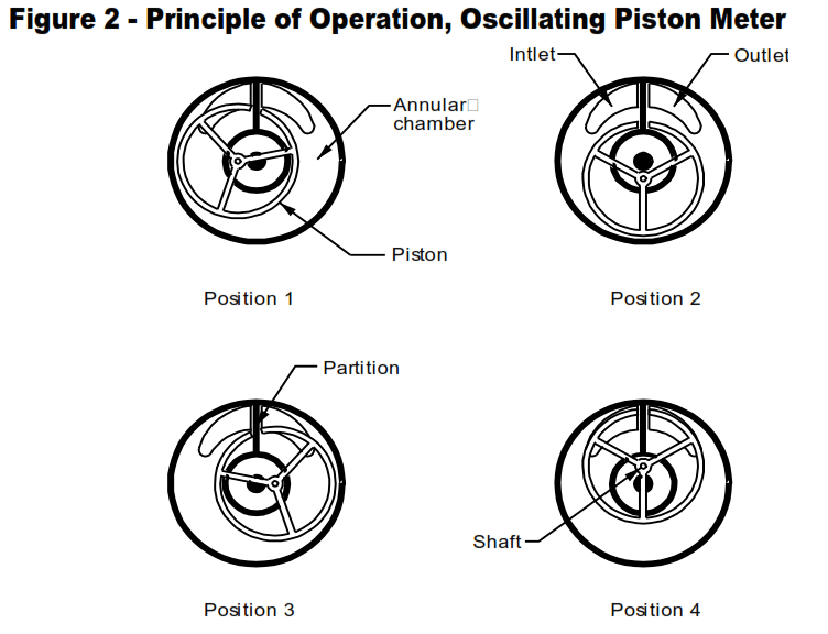
See Figure 2. In this meter, the hollow cylindrical piston and the annular chamber have the same height (except for the operating clearance). The diameters of the inner and outer walls of the chamber and the inner and outer diameters of the piston are dimensioned so the inner and outer surfaces of the piston always are in contact with the inner and outer chamber walls. The sealing of the measuring chambers depends upon the sliding contacts at the top and bottom of the piston and the combination of rolling and sliding line contacts between the piston and chamber walls. The partition prevents the Piston from rotating as it oscillates.
Entering liquid flows into the annular chamber, filling the spaces inside and outside of the piston (Position 1), and forces the piston into successive positions as shown. In Position 3, the liquid inside the
piston begins to discharge and continues to do so until the piston is between Positions 4 and 1, at which time the liquid outside the piston begins to discharge, continuing until the piston returns to Position 4. For each cycle, the meter displaces a volume equal to the volume of the annular chamber minus the volume of the piston. The shaft moves in a circular path, operating the secondary element.
- Materials of Construction
a. Housings: Cast iron, steel, aluminum, bronze, stainless steel, Alloy 20, phenolic-lined (acid service)
b. Pistons: “Teflon®,” Tefzel, carbon, hard rubber, Penton, Lexan, polypropylene, aluminum, bronze, Ni-Resist. - Sizes, Capacities, Accuracy
a. Connections: 3/8 inch to 2 inches
b. Capacities: Intermittent flow, ½ to 160 gpm, low viscosity lubricating liquids
c. Accuracy: + ¼ to 1 percent error, 5:1 to 10:1 ranges.
d. Repeatability: 0.05 percent - Pressure-Temperature Ratings (standard meters)
a. Maximum Pressure: 125 to 300 psig
b. Temperature Range: -45 to 120 °C (-50 to 250 °F) depending upon piston material. Meters for cryogenic service are available .
Working Principle Sliding Vane Meter
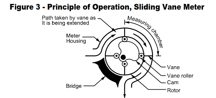
This type sometimes is known as a rotating vane meter but this designation is more logically applied to the types described in 4.4 and 5.1 where the vanes rotate without being extended or retracted as they rotate. In the sliding vane meter, Figure 3, the vanes slide in and out of the rotor as it rotates. As the liquid enters the meter, the vanes extend to enclose a precise volume in the measuring chamber. At the outlet, the vanes retract to permit the measured volume to leave the meter. The cam positions the vanes in the proper sequence, and the bridge wipes the surface of the rotor and prevents any incoming liquid from bypassing the measuring chambers. The sliding vane meter is capillary sealed, the vanes and rotor do not contact the base, cover, or housing of the meter during operation.
- Materials of Construction
a. Housings: Cast iron, ductile iron, steel, epoxy coated steel, stainless steel, nickel-coated steel
b. Internals: Stainless steel, combinations of steel and stainless steel, and ferrous and nonferrous (aluminum and bronze) metals, “Teflon®,” “Viton,” neoprene, or Buna N coated stainless steel. Solid “Teflon®” vanes are available.
Working Priciple Rotating Vane Meter (also known as Rotating Piston)
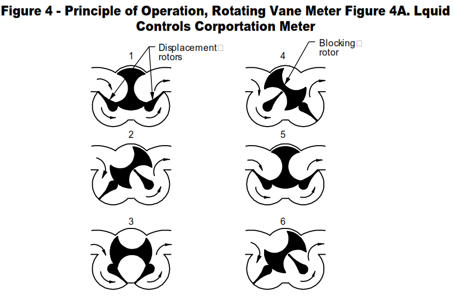
Figure 4A illustrates the principle of operation of the series of rotating vane meters. The meter contains two displacement rotors and a blocking rotor. The blocking rotor prevents any of the incoming liquid from bypassing the displacement rotors. The rotors are gear-synchronized so that blocking rotor makes one clockwise revolution to two counterclockwise revolutions of the displacement rotors. The displacement of the meter per one-half revolution of the blocking rotor is equivalent to the volumes of the two semicircular bores or measuring chambers in the body due to each one being swept once by a displacement rotor.
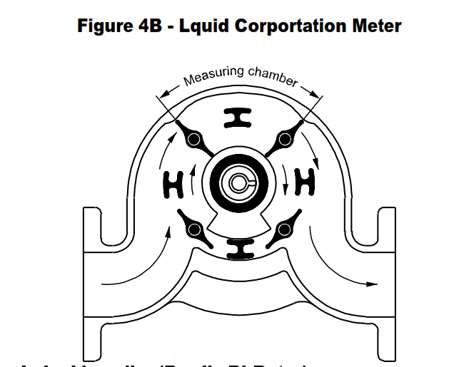
- Figure 4B shows the operating principle of a rotating vane meter. The rotation of the vanes forming the metering chambers is controlled by a cam. This meter is available in one size with 3-inch connections and a capacity range of 25 to 350 gpm. Suitable for a maximum working pressure of 125 psig, the meter housing is cast iron with a combination of stainless steel, steel, and aluminum internals.
- Materials of Construction
a. Housings: Aluminum, stainless steel, Ni-Resist
b. Rotors: Aluminum, stainless steel. Ni-Resist
- Sizes, Capacities, Accuracy
a. Connections: 1-1/2 inch to 6 inches
b. Capacities: Continuous flow, 5 to 1,000 gpm, low viscosity lubricating or nonlubricating liquids
c. Accuracy: +0.2 percent error, 10:1 to 20:1 ranges.
d. Repeatability: 0.02 percent
- Pressure-Temperature Ratings (standard meters)
a. Maximum Pressure: 150 and 300 psig
b. Temperature Range: -35 to 95 °C (-30 to 200 °F). Meters for cryogenic service are available.
Working Principle Lobed Impeller Meter (Brodie Bi-Rotor)
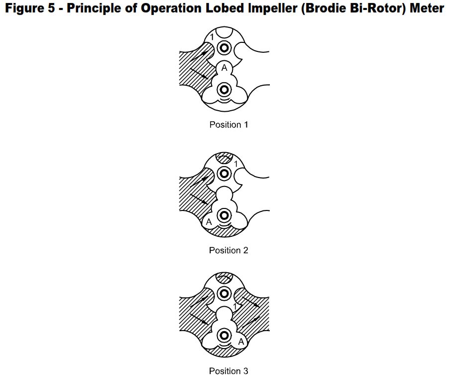
Figure 5 illustrates the principle of operation of the lobed impeller meter. The two-spiral-fluted rotors are gear-synchronized to rotate in proper relationship and without metal-to-metal contact. The measuring chambers are formed by adjacent rotor lobes and the chamber walls. Capillary seals between the rotors prevent the entering liquid from bypassing the measuring chambers. Also, the liquid is confined in the measuring chambers by capillary seals between the rotor tips and chamber walls.
- Materials of Construction
a. Housings: Aluminum, steel, ductile iron, nickel cast iron
b. Rotors: Aluminum, nickel cast iron - Sizes, Capacities, Accuracy
a. Connections: 1-1/2 inches to 12 inches
b. Capacities: Continuous flow, 5 to 3,500 gpm, low viscosity lubricating liquids
c. Accuracy: + 0.2 to 0.4 percent error, 5:1 to 10:1 ranges.
d. Repeatability: 0.02 percent. - Pressure-Temperature Ratings
Maximum Pressure: 125 to 1,440 psig for most sizes
Temperature Range: -20 to 65 °C (0 to 150 °F). Meters suitable for 160 and 230 °C (325 and 450 °F) are available
Working Principle Oval Gear Meter and Helical
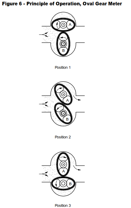
The metering elements are precision machined oval-shaped gears which are rotated by the differential pressure across the meter, Figure 6. The meshed gears seal the inlet from the outlet flow, developing the differential pressure. In Position 1, the differential pressure exerts a torque on Gear A, but the torques on Gear B cancel each other. The torque causes Gear A to rotate, driving Gear B as shown in Position 2. In Position 3, the torques on Gear A cancel each other and the torque on Gear B causes it to rotate, driving Gear A. As the gears rotate, capillary seals between the gears and the walls of the crescent-shaped measuring chambers trap precise quantities of the liquid in the chambers. The meshed gears prevent the entering liquid from bypassing the measuring chamber.
- In helical Positive Displacement Flowmeters, the fluid pressure causes two precision machined helical rotors to turn. As the rotors rotate, progressive cavities of fluid are formed displacing known fixed volumes between the rotors. The rotation is thus precisely proportional to the volume of fluid being displaced.
- Materials of Construction
a. Housings: Cast iron, steel, bronze, stainless steel, hard rubber lined
b. Rotors: Cast iron, bronze, stainless steel, hard rubber-covered aluminum - Sizes, Capacities, Accuracy
a. Connections: 3/8 inch to 10 inches
b. Capacities: Intermittent flow, 0.1 to 5,000 gpm, low viscosity lubricating liquids
c. Accuracy: + 0.5 percent error, 2.5:1 to 16:1 ranges.
d. Repeatability: 0.02 percent. - Pressure-Temperature Ratings
a. Maximum Pressure: 100 to 1,450 psig - b. Temperature Range: -5 to 110 °C (20 to 230 °F). Meters for temperatures up to 315 °C (600 °F) are available
Working Principle Reciprocating Piston Meter
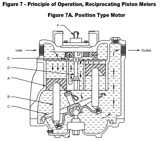
The Reciprocating Piston Meter has the highest pressure drop and is the most complicated and expensive meter. Also, it is the most accurate. In its simplest form, it consists of a single cylinder which is alternately filled and emptied. Figure 7A illustrates a common design consisting of cylinders arranged in a circle and fitted with straight thrust pistons, A. The pistons ride on piston rods, B, connected to a geared control plate, C, which is pivoted in the center.
The control plate maintains the alignment of the piston rods and controls the piston stroke lengths. As incoming liquid forces a piston downward, lever action of the control plate raises the opposing piston, discharging a measured volume. The nutating motion of the gear plate resulting from the successive operation of the pistons, rotates the drive shaft, D, which rotates the sliding valve, E, to open and close the cylinder ports in the proper sequence. The extension, F, of the drive shaft operates the secondary element.
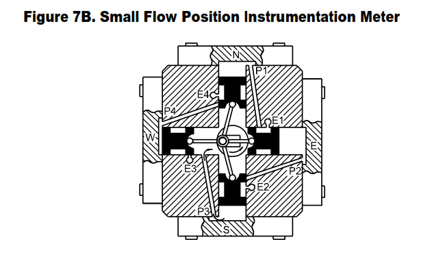
- Figure 7B shows the internal arrangement of a typical low capacity reciprocating piston meter. The four radial pistons (black) are connected to and drive the crankshaft in a clockwise direction. A cylindrical permanent magnet attached to the crankshaft drives a hollow cylindrical magnet attached to the drive shaft of the secondary element. As shown, the liquid (gray) entering the center of the meter and surrounding the crankshaft, is flowing through port P3, forcing the south piston upward. The west piston has just reached the end of its travel and is about to be forced to the right by
the liquid which will be admitted through port P4 by the upward moving north piston when it uncovers the port inlet. The north piston is exhausting measured liquid through ports P1 and E1. When the north piston reaches the end of its travel, the east piston will have moved to the right, closing E1 and opening the inlet to P1 to permit liquid to enter and force the north piston downward. It will be noted that each piston acts as a 3-way valve for its counterclockwise adjacent piston. - Materials of Construction
a. Housings: Cast iron, ductile iron, bronze stainless steel (low capacity meters: aluminum, stainless steel)
b. Internals: Combinations of stainless steel and “Teflon®” with carbon pistons, stainless steel with “Teflon®” pistons, steel and stainless steel with Rulon pistons, Ni-Resist and stainless steel with Rulon pistons,all iron and steel, bronze (low capacity meters: all stainless steel, Ni-Resist cylinders with aluminum pistons, carbon cylinders with stainless steel or titanium pistons). - Sizes, Capacities, Accuracy
a. Connections: ¾ inch to 3 inches (low capacity meters: ¼ inch and 3/8 inch)
b. Capacities: Continuous flow, 0.2 to 250 gpm low viscosity lubricating and nonlubricating liquids (low capacity meters: continuous flow, 0.15 to 90 gph, low viscosity
c. lubricating and nonlubricating liquids)
d. Accuracy: + 0.1 to 2 percent error, 5:1 to 200:1 ranges. (Low capacity meters: + 0.3 to 5 percent, 20:1 to 300:1 ranges)
e. Repeatability: 0.02 percent.
- Pressure-Temperature Ratings
a. Maximum Pressure: 125 to 500 psig (low capacity meters: to 800 psig)
b. Temperature Range: -30 to 120 °C (-20 to 250 °F) [low capacity meters: -30 to 95 °C (-20 to 200 °F)]
Check out this article Part I.
Positive Displacement Flowmeters Design Requirement in Process Industry
Check out this article Part II.
Liquid Positive Displacement Flowmeters Design Requirements
Check out this article Part III.
Main keywords for this article are Liquid Positive Displacement Flowmeters Design Requirements, Working Principle Nutating Disk Meter, Working Principle Oscillating Piston Meter, Working Principle Sliding Vane Meter , Working Priciple Rotating Vane Meter, Working Principle Lobed Impeller Meter, Working Principle Oval Gear Meter, Working Principle Reciprocating Piston Meter.
