This article is about common problem and cases to understand LTE handover optimization.
1. Neighbor Missing.
Generally speaking, neighbor missing can be found by checking the radio parameter list and the test data, or tracing the signaling at the background to confirm whether the source eNB has issued a handover request to the destination eNB upon the reception of the measurement report. In some cases, however, we have some difficulty in getting the radio parameter list and tracing the background signaling. Under this circumstance, we can analyze whether it is the problem of neighbor missing by checking the foreground signaling.
LTE is a self-optimizing network in protocol. The measurement report from the UE will be reported in accordance with a3 event decision rule. The reported cells are not related with the neighbor cells in the measurement control. Thus we can determine whether the problem is neighbor missing by comparing the measurement report of the exceptional handover point with the neighbor cell in the measurement control of the current serving cell.
1. Analyzing Neighbor Missing at the eNB Side.
Repeated Measurement Reports.
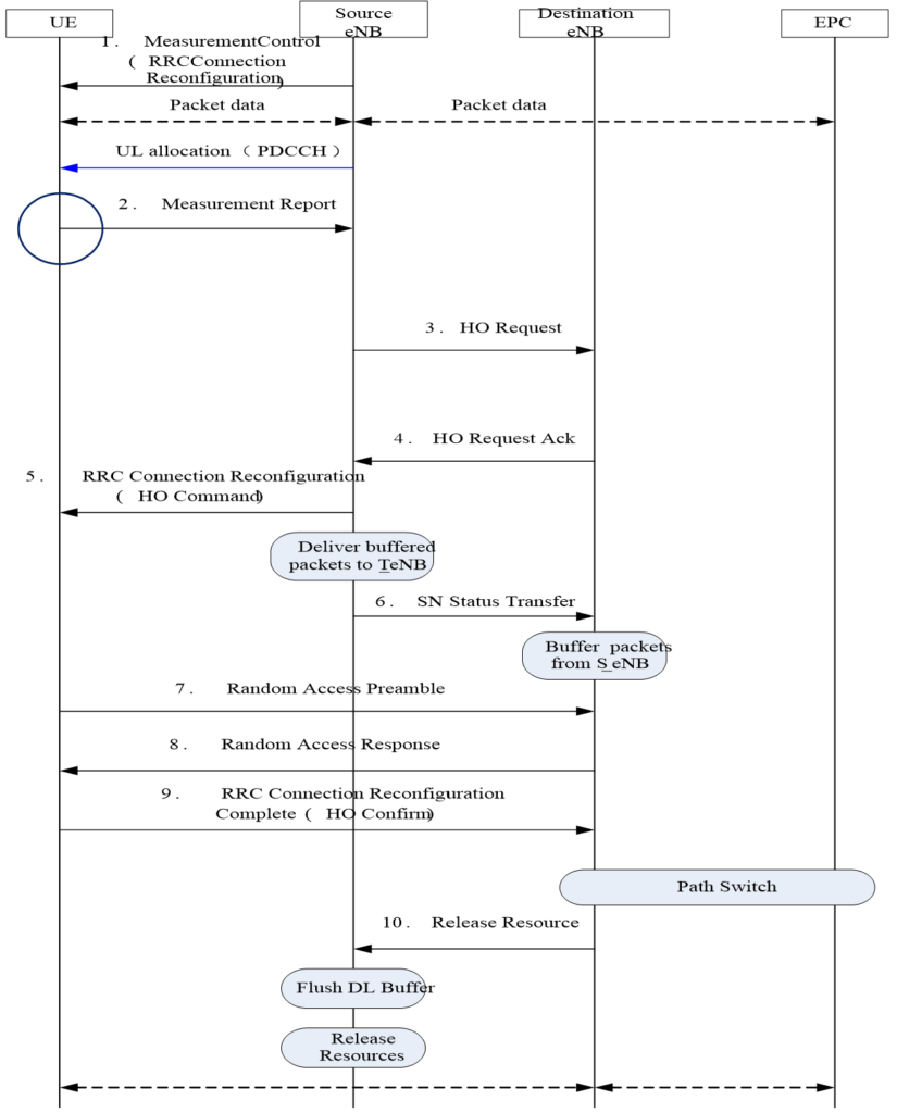
In normal process, the eNB will send handover command soon after the UE sends the measurement report. But if neighbor missing exists, the source eNB will not be informed of the destination eNB information and cannot complete the step 3 of the handover process call flow diagram, handover command will not be sent. Since the UE is still in process, with the signal becoming weaker and weaker and the cells that meet the a3 event condition getting more and more, and new measurement reports are triggered continuously. The eNB will not send handover command properly until there are neighbor cells.
Analyze this problem with the following typical example:
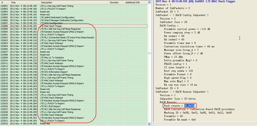
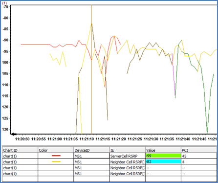
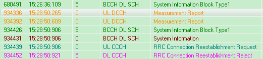
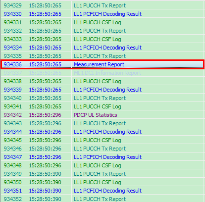
The phenomenon as shown in Figure 1 was found during a drive test. The PCI (PhysCellId) of the first three measurement reports are all 28 (The first three measurement reports have the same PCI and a little different in RSRP measured result, as shown in Figure 2). In the fourth measurement report (as in Figure 3), there are two cells: PCI28 and 19. From the measured value, we can see that 28 is three dBs higher than 19. The handover command (as in Figure 4) is received immediately behind them, in which the destination PCI is 19 instead of 28. We can primarily determine that 28 is the missing neighbor cell.


Figure 4. Handover Command.

Figure 5. Measurement Control Message of the Source Cell.

No Response upon the Sent Measurement Report.
In above section introduces multiple measurement reports as a result of neighbor missing. No handover command will be received until the destination cell reported in the measurement report is adjacent to the source cell. But if the measurement report loss synchronization before the eNB gives a response, re-establishment will be launched and the UE reports call-drop.
The analysis method for this phenomenon is basically identical to above section.
Analyze this problem with the following typical example:
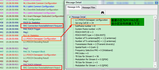
During a drive test, it is found that the UE had not received the handover command after sending the measurement report. This caused the connection re-establishment due to radio link failure (as shown in Figure 6). First, checked the details of the measurement report (Figure 7 shows that PCI of both the measurement reports are 30), destination PCI is 30; when checked the source measurement control (as shown in Figure 8), found that no neighbor cell is configured.
Figure 6. Call-drop Caused by Neighbor Missing.

Figure 7. 1st Measurement Report.

Figure 8. Measurement Control Information of the Source Cell.

2. Impact of Parameter Adjustment.
Traffic Decrease.
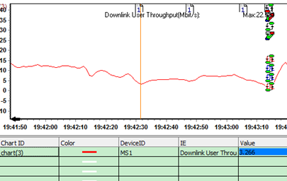
In the four measurement reports introduces in Section above, it is obvious that the SINR becomes worse (Figure 9) and traffic rate decreases (Figure 10) as a result of failure to hand over in time.
Figure 9 SINR.

Figure 10 Traffic.
Call Drop.
What is introduced in 4.1.1.2 is call drop caused by no response to the measurement report. This problem will have an impact on call drop rate, traffic rate, and other indicators.
3. Handling of Neighbor Missing.
Adding neighbor cell can solve the problem.
For some special road sections, it is required to delete some neighbor cells and adjust the power. Refer to below section for details.
2. Handover Exception Caused by Radio Environment.
Access Difficulty at the Destination Side Due to Uplink Interference
This section introduces the case of low handover and access success rate caused by severe uplink interference of cells in other sites, which is a result of GPS exception.
Problem Description.
We experienced the problem of access failure and call drop after handover a lot during testing Fukuoka network indexes and it appeared irregularly. The call-drop points found in the test are as shown in the figure below:
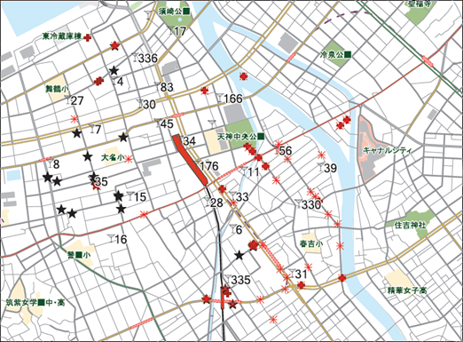
From the above distribution graph of call-drop points, we can see that most of the call-drop points are in the southeast.
The index of this long call is as listed in the table below:
| Total | KPI Type | Correspond | Attempt | Ratio |
| 1 | Random Access Success[%] | 207 | 215 | 96.28 % |
| 2 | RRC Connect Success[%] | 38 | 41 | 92.68 % |
| 3 | Initial Access Success[%] | 0 | 0 | 0.00 % |
| 4 | E-RAB Connect Success[%] | 44 | 44 | 100.00 % |
| 5 | Call Drop[%] | 26 | 44 | 59.09 % |
| 6 | HO Success[%] | 106 | 130 | 81.54 % |
The statistics data above shows that both call drop rate and handover success rate are very bad.
Problem Analysis.
1. As for this problem, we conducted call quality test to some cells and found that the network cannot be connected all the time. The Qualcomm UE indicator flashes between red (exception) and green alternately. Besides, the self-developed UE is also unable to access to the network.
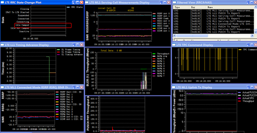
The performance of self-developed UE is as below:

The self-developed UE kept trying to access the network and failed all the time. It appeared frequently from RRC request to RRC release.
The Qualcomm UE acted as the same. It was unable to access, just pingpong handover before IDLE and CONNECTED.
2. When checked the test LOG, we found in the serving cell that RRC connection re-establishment was rejected.

We checked the call-drop and reestablishment processes using the Qualcomm analysis software QCAT and found that it was because DC10 not arrived after UL_DATA, RS reached the maximum number and triggered MSG1 which was failed to be sent after tried for 8 times as it was unable to reach the network side, and finally, reestablishment is triggered.
To verify whether the problem is regular, we performed CQT (Call Quality Test) and the area under test is as shown in Figure 15.
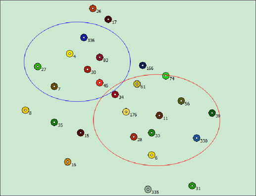
The cells within the blue circle had a relatively high random access and handover success rate. The ones in the red circle had some difficulty to access. It failed after RRC reconfiguration in handover test, and reestablishment is subsequently triggered and rejected. Access failed again.
From the above analysis, we preliminarily concluded that it was caused by uplink data exception which was the result of interference. At present, Fukuoka site employs GC site, one BBU with multiple RRUs hooked up to it forms a site. Japan uses omni site and the sites are distributed as shown in Figure 16.
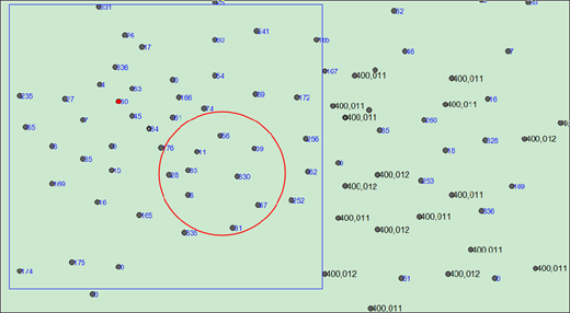
The red area is the centralized call drop area. Since this current test stage was the preliminary performance test stage, it was just done around the Ref area (inside blue box area in the figure above). Later we found that the call-drop area was somewhat related with the BBUID. The area no call drop falls within the BBUID=400010. The area close to the call-drop area are the cells under the BBUs with BBUID=400011 and 400012. So we doubted that the problem is caused by something related to BBUID.
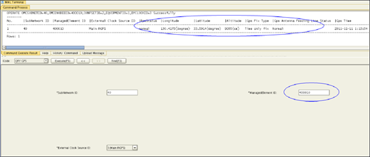
3. After the above analysis, we checked the background equipment alarm. First we checked GPS status and found that 400010 and 400012 sites worked properly. But GPS of 400011 sites were not locked.
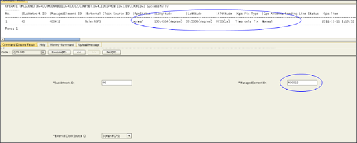
GPS status of 400010 and 400012 sites is normal:
Figure 17. Background Query Graph of Normal GPS.

GPS of 400011 sites is not locked:
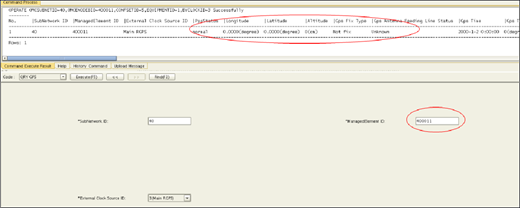
400011 and 400012 sites were distributed in a mixed way. Because GPS of 400011 sites was not locked, the cells under it might have GPS interference to the surrounding cells which result in other cells failure in uplink access. Later we checked the uplink received power data of the failure cells using MTS tracing and found that the received power of the cells at the eNB side was raised (generally it should be between -96~99dbm) to about -80dbm. It was obviously disturbed by uplink interference. The interference data is as list below:
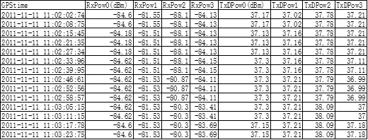
RxPow 0~3 received at the eNB side was very high. Uplink interference was severe.
4. With the above step-by-step analysis, we can roughly determine that the problem was caused by the GPS losing lock of BBUID=400011 sites, which resulted in interference to other cells. By checking from the background we got the information that the GPS status of 400010 and 400012 sites worked properly without any problem. But the BBU of 400011 did not power up GPS at all but with radio wave signals being sent. This resulted in the interference to the surrounding cells. When we tested again with all cells of 400011 blocked, some cells of 400010 still had problem in access. We extracted the received uplink power for analysis, there was still some interference.
Workaround and Verification
We studied the access mode of cells connected to the BBUs of Fukuoka and found that, Japan Fukuoka uses GC site mode at preset. One BBU manages all of cells under it, with each BBU sharing one GPS signal source. Although the GPS shared by the sites under 400012 was powered on, occasional GPS losing lock still happened once in a while which caused some other cells under 400012 which are close to 400010 also get disturbed. Consequently, when we tested again with all the sites under the 2 BBUs of 400011 and 400012 blocked, the problem disappeared. All cells under 400010 accessed successfully. The problem was solved.
Conclusion
The above analysis shows that GPS failure has severe interference to the surrounding sites. If GPS not switched on, waves can never be released. For occasional GPS losing lock, it is necessary to control its interference to other sites through parameter adjustment. There is control scheme for GPS losing lock problem at the background, which consists of the following two parameters:
A. GPS holdover time-out switch Enable/Disable
B.GPS holdover time-out switch 60 minutes ~ 4 hours
These two parameters should be configured at the EMS-eNodeB configuration table. Set the first parameter as Enable and then specify the hold-over time, default is 60 minutes, as shown in Figure 19.

Holdover time-out switch at Enable and holdover time-out threshold at 60 minutes means that the switch is turned on, and the cell will be turned off if GPS not synchronized within 60 minutes.
Holdover time-out switch at Disable and holdover time-out threshold at 60 minutes means the switch is turned off and cell status will not be related with whether the GPS is synchronized, it will always keep normal establishment status.
Handover Problems Caused by Complex Environment.
Characteristics of Japan T1 Network
- All cells installed with omni-directional antennas
- High density of sites
- Complex environment
Since co-locate with PHS sites, omni antenna is used. This makes engineering parameter adjustment impossible. To ensure the coverage of indoor, the density of sites is very high. Further to this, the environment of cities in Japan is relatively complex. Consequently, the RSRP is good but SINR is usually bad, especially in the vicinity of crossroads where pilot pollution is heavy. We do our job mainly focusing on these failure points.
Optimization Method
- Avoid handover at crossroads: Avoid handover at crossroads as much as possible. If inevitable, bring forward or postpone the handover by adjusting parameters, or set one-way neighbor cells as necessary, which is not recommended however in general situation except for some road sections where KPI is really unable to be solved. Radio parameter adjustment should be done in a flexible way based on the main rule of minimizing the influence to other normal areas when optimizing handover.
- Reduce handover produced by overshooting: adjust the coverage preferentially, if coverage cannot be adjusted, avoid handover as much as possible. If these two methods do not work, add neighbor cells and adjust handover parameter.
Case Analysis.
This section introduces the optimization method by using three typical cases.
Case 1: Promote coverage by increase cellA and cellC RS power of normal handover cells, reduce the RS power of cellB whose power goes up or down abruptly at crossroads, so as to lessen the unnecessary handover.
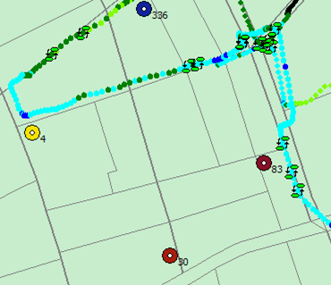
Test route is as shown in Figure 20.

Figure 20. Handover Failure Point Caused by Coverage1.
The UE moves along the blue route. The UE is supposed to hand over from the PCI=336 cell to the PCI=83 cell. But at the location indicated by the red cross, the RSRP of the PCI=4 cell goes up abruptly and it goes down abruptly after the UE hands over to the PCI=4 cell. The UE cannot receive the handover command and call drop occurs.
RSRP Line Chart is as shown in Figure 21:
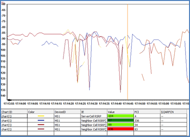
RSRP Line Chart of the PCI=4 cell is indicated as the red circle in the above figure.
The signaling of call drop during handover is as shown in Figure 22.

The process of optimization is as below:
Since this cross road is the handover point of PCI=336 and PCI=83 cells, increase the RS Power of the PCI=83 cell to make it cover this cross road and make the handover of the 83 cell and the 336 cell not happen exactly at this cross road.
Case 2: Change the individual offset of neighbor cells CellB and cellC to make the UE hand over to the destination cell cellC in advance, so as to avoid call drop.
Test route is as shown in Figure 23:
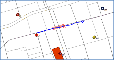
The UE moves along the blue route. The UE is supposed to hand over from the PCI=45 cell to the PCI=61 cell. But this cross road is covered by PCI=34 cell. After the UE passing by the crossing, the RSRP of the PCI=34 cell goes down abruptly which results in no handover command is received after the US sending the measurement report and call drop occurs.
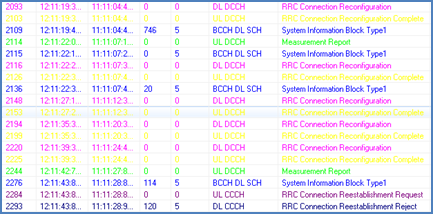
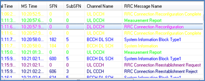
The signaling of call drop during handover is as shown in Figure 24.
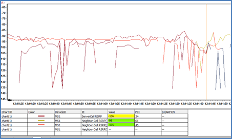
RSRP Line Chart of the place where call drops is as shown in Figure 25.
The process of optimization is as below:
The call drop caused by rapid degradation of PCI=34 cell signal can be avoided by adding 3dB to the CIO of PCI=34 cell and PCI=61 cell to move the handover point west and bring forward the UE handover to 61 cell.
Case 3: Test route is as shown in Figure 26:

The UE moves along the blue route. The UE is supposed to hand over from the PCI=45 cell to the PCI=8 cell. But at the location indicated by the red cross, the UE hands over to PCI=4 cell. Call drop occurs when hand over from PCI=4 back to PCI=45.
The signaling of call-drop during hadover is as shown in Figure 27:
RSRP Line Chart of the handover call-drop point is as shown in Figure 28:
The process of optimization is as below:
In order to present the UE from switching to the PCI=4 cell, we tried both reducing the RS Power of the PCI=4 cell and adjusting the individual offset CIO of PCI=45 and PCI=4 cells successively, but the RSRP of the PCI=4 cell is 17dB stronger than that of the PCI=45 cell, the call-drop problem was still there. After analyzing the RSRP distribution around the cross road, the southeast of the cross road is covered by the PCI=45 cell, and the north by the PCI=4 cell. But the RSRP of the PCI=7 and the PCI=4 cells around the cross road are almost the same, as shown in the table below:
Deleting the one-way neighbor cell PCI=45 and PCI=4 can avoid handover to PCI=4 cell on this test route, the UE can also handover to PCI=7 cell before to PCI=4 cell when moving from the cross road toward PCI=4.
2. Call-Drop Caused by Uplink Asynchronization.
Problem Description
During the test, we found that the UE launched re-establishment which was rejected when arrived at the location indicated with blue box.

Problem Analysis
During the signaling check, we found that the measurement report was sent twice before re-establishment but no handover command was received. This resulted in the UE out of synchronization and re-establishment was rejected.
We opened the diagnosis signaling and found that the UE has already requested scheduling before sending the measurement report, but it has not received any PDCCH scheduling acknowledgement, that is, SR request failed.
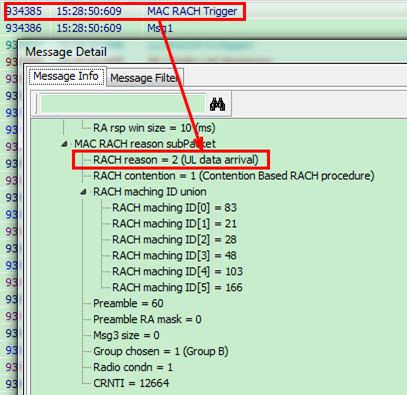
The source cell initiated random access when the maximum number SR sending is reached. We checked the MAC RACH Trigger signaling, the cause value of sending random access was “UL data arrival”, that is, the random access was launched to restore the uplink which was failed due to the SR request failure and MR sending failure.
During the whole random access process, all MSG1s sent at the source cell did not get RAR received.

When MSG1 was sent for the maximum number of times, that is, when recovering the uplink at the source cell failed, it went into the reestablishment process. The cause value of the reestablishment is “Radio link failure”.
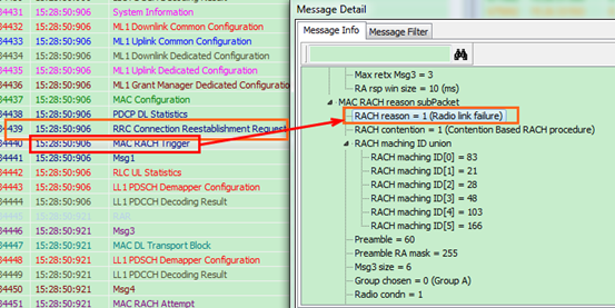
However, cell selection is necessary for reestablishment. Because the selected cells did not have the context message of the UE, reestablishment was rejected and call-drop occurred.
Workaround and Verification.
The “UL data arrival” problem always occurs at the weak filed of the source cell. For handover, it can be solved by bringing forward the handover to other cells with better signal quality.
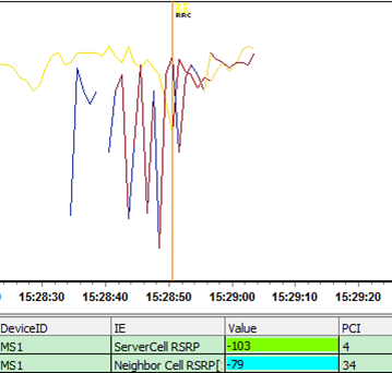
We checked the RSRP changing and found that the strength of the source cell drops down suddenly in a very short time and that of neighbor cells rises abruptly, we need to decrease the Time to Trigger of the current network, as it will not make any big difference if we just adjust the individual offset of the entire cell at this moment.
The Time to Trigger was 320 in the current network configuration. We tried to shorten the time for a3 event decision by changing the Time to Trigger to 256ms and tested it for several times, now the problem disappeared.
Conclusion.
From the diagnosis signaling of the current versioned CNT, we can see the detailed Qualcomm internal signaling. Most common problems can be located through the analysis of signaling. When handling the problem, we should adjust parameters according to the situation of field flexibly, thus to optimize the handover.