LTE (Long Term Evolution) network architecture is designed to provide high-speed data transmission and efficient management of voice and data services. Below is a details and overview of the LTE network architecture:
1. Evolution of Cellular Networks.
Mobile networks have been evolving for many years. The initial systems, referred to as “First Generation,” were launched commercially at the end of the 1980s. The pressure for greater capacity, more security, and roaming saw these replaced with “Second Generation” solutions, and more recently with “Third Generation” systems. Today, the growth in mobile broadband has promoted the development of 4G or “Fourth Generation” systems.
First Generation (1G) mobile systems used analogue modulation techniques. These analogue systems were proprietary and based on Frequency Modulation. Due to this, they all lacked security, any meaningful data service, or international roaming capability. The main commercial systems deployed around the world included AMPS, TACS, and ETACS.
AMPS, the first AMPS system, appeared in 1976 in the USA. From its initial commercial launch, it was mainly implemented in America, Russia, and Asia. Various issues, including weak security features, made the system prone to hacking and handset cloning.
TACS, the European version of AMPS, had slight modifications, including its operation on different frequency bands. It was mainly used in the UK, as well as parts of Asia.
ETACS, an improved version of TACS, enabled a greater number of channels and, therefore, facilitated more users.

3GPP Evolution before LTE.
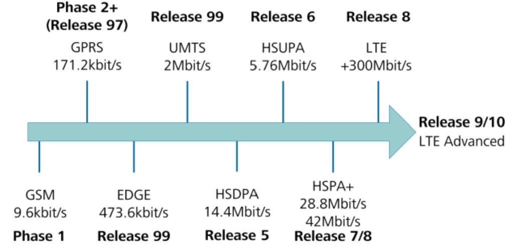
The development of GSM, GPRS, EDGE, UMTS, HSPA, and LTE, as well as the strategy for future mobile networks, has been coordinated and planned by the various parties within the 3GPP working groups. This development roadmap is based on a series of specification releases, marking key milestones in mobile network evolution. These milestones began with the introduction of GPRS in Release 97 and chart the evolution of 3GPP networks up to the introduction of LTE and beyond.
Pre-Release 99 saw the introduction of GSM and the addition of GPRS. The main GSM phases and 3GPP releases include GSM Phase 1, GSM Phase 2, GSM Phase 2+ (Release 96), GSM Phase 2+ (Release 97), and GSM Phase 2+ (Release 98).
3GPP Release 99 saw the introduction of UMTS and the EDGE enhancement to GPRS. UMTS contains all the features needed to meet the IMT-2000 requirements as defined by the ITU. It is capable of supporting circuit-switched (CS) voice and video services, as well as packet-switched (PS) data services over common and dedicated bearers. Initial data rates for UMTS were 64 kbit/s, 128 kbit/s, and 384 kbit/s, with a theoretical maximum of 2 Mbit/s.
A Heterogeneous Network, or HetNet, involves the use of different types of base stations (macro, micro, pico, relay) operating on various technologies (GSM, WCDMA, and LTE) within the same network. This approach aims to provide the excellent coverage and high capacity that end-users expect from their operators. This concept is in contrast to ‘homogeneous’ networks, or HomoNets, which are primarily built using one type of base station, often macro.
Huawei introduced the next-generation LTE-B (Release 12/Release 13) network architecture known as FusionNet at the Mobile World Congress (MWC) 2013 in Barcelona. FusionNet combines multi-system, multi-band, and multi-layer heterogeneous networks, significantly improving cell edge user throughput by 500%, thus creating borderless networks.
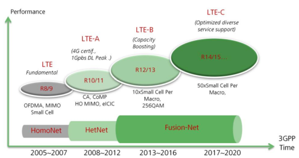
The core of FusionNet is based on LTE-B techniques such as multi-flow aggregation, interference coordination, service adaptation, and spectrum efficiency optimization. By integrating existing LTE and LTE-A techniques (such as multi-point coordination and carrier aggregation), FusionNet achieves deep integration of multi-system, multi-band, and multi-layer networks. This integration helps operators significantly reduce CAPEX (capital expenditure) and OPEX (operational expenditure), allowing users to enjoy ultra-broadband, zero-waiting, and ubiquitous connectivity.
LTE Technical Objectives.
| LTE Requirements from ITU | LTE Technical Features from 3GPP. |
| Flexible bandwidth | 1.4MHz, 3MHz, SMHz, 10Mhz, 15Mhz, 20MHz |
| Higher spectrum efficiency. | DL: S(bit/s)/Hz, 3-4 times than R6HSDPA UL: 2.5(bit/s)/Hz, 2-3 times than R6HSDPA |
| Higher peak throughput (@20MHz) DE 100Mbps, UL: 50Mbps | DL: 100Mbps, UL: 50Mbps |
| Control plane:< 100ms, User plane: < 10ms | Control plane:< 100ms, User plane: < 10ms |
| Shall support stationary/pedestrian/vehicular/high speed vehicular. | Shall support high speed vehicular (>350km/h) for 100kbps access service. |
| Support inter-system handover. | Support interoperability between 3GPP existed and non- 3GPP |
| VoIP Capacity. | Remove CS domain, CS service realized in PS domain which can support multiple service, especially voice service (such as VoIP). |
| Decrease network evolution cost. | Remove BSC/RNC. |
| Reduce CAPEX and OPEX. | SON. |
2. EPC Architecture.
In the evolution of the core network, the packet domain of the core network evolves into the System Architecture Evolution (SAE), also commonly referred to as the Evolved Packet Core (EPC). EPC is based entirely on the packet domain and no longer supports the circuit domain. The LTE network features a flat architecture characterized by several key elements.
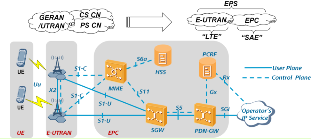
Firstly, the Radio Network Controller (RNC) is removed from the radio access network, leaving the NodeB as the sole network element in this domain. In the core network, the MSC server and Media Gateway (MGW) are eliminated, and voice services are provided based on IP. The packet-switched domain of the core network adopts an architecture similar to that of a softswitch, separating the control plane from the user plane.
In this architecture, the Mobility Management Entity (MME) is responsible for storing UE contexts on the control plane, including the ID, status, and tracking area of the UE. It also manages and allocates an ID to a UE and performs functions such as mobility management, authentication, key management, encryption, and integrity protection. The Serving Gateway (SGW) provides functions like paging, information management for a UE in idle state, mobility management, encryption on the user plane, PDCP, SAE bearer control, and encryption and integrity protection for NAS signaling. Notably, the network is an all-IP network.
This design choice is driven by the need to meet low-delay requirements, which are less than 10ms on the radio network side. Additionally, an all-IP network offers the lowest costs due to the maturity of VoIP technology. This streamlined architecture is essential for supporting the efficient and high-speed data transmission that modern mobile networks demand.
EPC Network Architecture -2G/3G Co-existence.
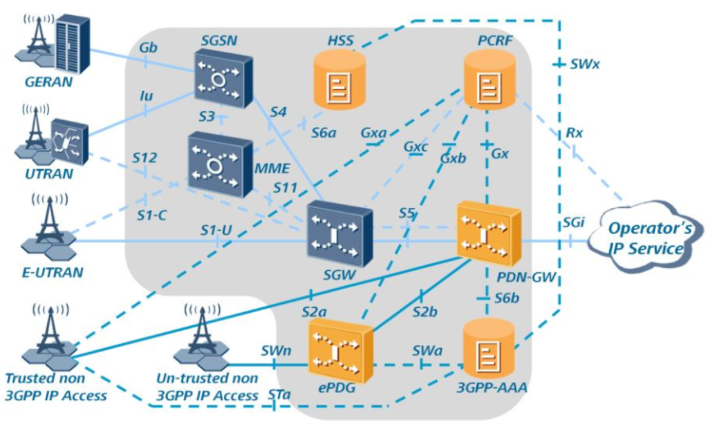
In the Evolved Packet Core (EPC) network, all interfaces within the EPC and those extending to functions outside of it are denoted by the letter “S” and utilize IP services. Key elements supporting LTE operation, aside from the MME (Mobility Management Entity), S-GW (Serving Gateway), and PDN-GW (Packet Data Network Gateway), include the HSS (Home Subscriber Server), PCRF (Policy and Charging Rules Function), and ePDG (evolved Packet Data Gateway). The RNC (Radio Network Controller) and SGSN (Serving GPRS Support Node) may also be involved.
The HSS serves as a “master” database, though it is often comprised of several physical databases to accommodate the number of subscribers and redundancy requirements. It holds variables and identities crucial for supporting, establishing, and maintaining calls and sessions made by subscribers.
The PCRF provides functionalities related to policy control and charging control. It manages bearer network control in terms of Quality of Service (QoS) and the allocation of associated charging vectors.
The ePDG is used when connecting to Untrusted Non-3GPP IP Access networks. It offers functionalities such as allocating IP addresses and encapsulating/de-capsulating IPSec and PMIP tunnels, ensuring secure and efficient data transmission between the LTE network and external IP networks.
UE Related Information.
User Equipment (UE) in mobile networks is identified by several types of identities. These include the IMSI (International Mobile Subscriber Identity), which uniquely identifies a subscriber, and the IMEI (International Mobile Equipment Identity), which uniquely identifies the equipment itself. The GUTI (Globally Unique Temporary Identity) is used to enhance privacy by temporarily identifying the user within the network. The S-TMSI (SAE-Temporary Mobile Subscriber Identity) is another temporary identifier used within the System Architecture Evolution (SAE).
UE Categories and capabilities.

The IP address, which can be in either IPv4 or IPv6 format, is used for data transmission over the internet. The GUTI is composed of the GUMMEI (Globally Unique MME Identifier) and the M-TMSI (MME-Temporary Mobile Subscriber Identity). The GUMMEI consists of the MCC (Mobile Country Code), MNC (Mobile Network Code), and MMEI (MME Identifier). The MMEI itself is made up of the MMEGI (MME Group Identifier) and the MMEC (MME Code).
Therefore, the full composition of GUTI can be represented as follows: GUTI = GUMMEI + M-TMSI, which expands to GUTI = (MCC + MNC + MMEI) + M-TMSI, further detailed as GUTI = (MCC + MNC + (MMEGI + MMEC)) + M-TMSI,
and ultimately simplified to GUTI = (MCC + MNC + MMEGI) + S-TMSI. The S-TMSI itself is a combination of the MMEC and the M-TMSI.
Functions of eNodeB.
The eNodeB (E-UTRAN Node B) in LTE networks hosts a variety of crucial functions. One key identity it manages is the TAI (Tracking Area Identity), which consists of a group of neighboring cells defined by the operator. Within this area, there is no need for a location update, similar to the RAI in 2G/3G networks.
Another important identity is the EUTRAN CGI (Evolved UTRAN Cell Global Identity), composed of the MCC (Mobile Country Code), MNC (Mobile Network Code), eNB Id, and Cell Id.
ECG=MCC +MNC + eNB Id + Cell Id
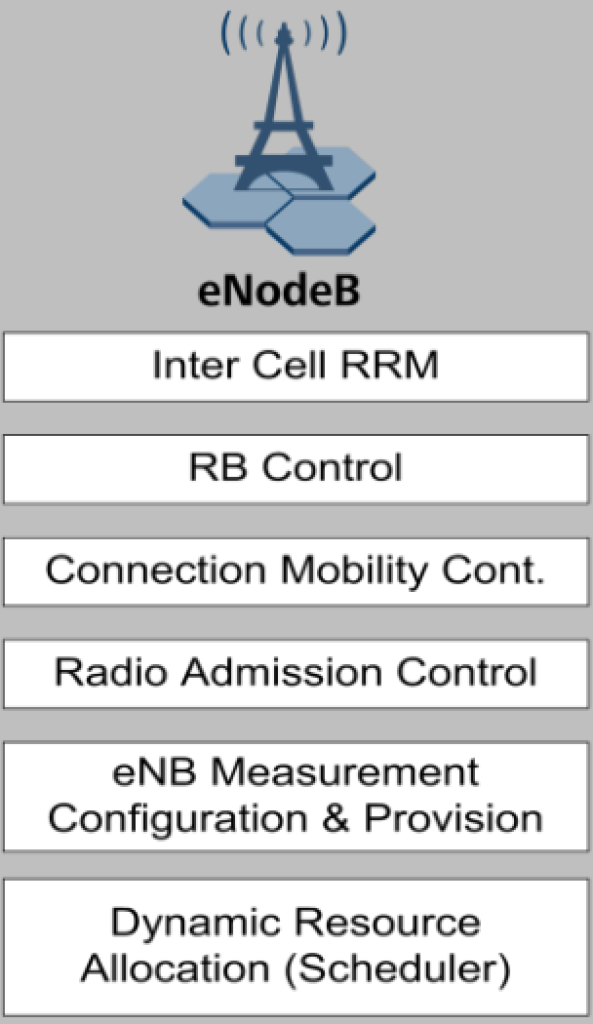
In terms of functionality, the eNodeB is responsible for several key tasks.
It performs Radio Resource Management, including Radio Bearer Control, Radio Admission Control, Connection Mobility Control, and the dynamic allocation of resources to UEs in both uplink and downlink through scheduling.
Additionally, the eNodeB handles IP header compression and encryption of the user data stream.
The eNodeB also plays a role in the selection of an MME during UE attachment when no routing to an MME can be determined from the information provided by the UE. It routes User Plane data towards the Serving Gateway and is responsible for scheduling and transmitting paging messages, which originate from the MME.
Furthermore, the eNodeB schedules and transmits broadcast information from the MME or O&M, configures measurements and measurement reporting for mobility and scheduling, and manages the scheduling and transmission of PWS (Public Warning System) messages, which include ETWS (Earthquake and Tsunami Warning System) and CMAS (Commercial Mobile Alert System) messages originating from the MME.
Functions of EPC Main Elements.
| MME | Serving Gateway | PDN Gateway |
| Mobility Management. | Packet forwarding and routing. | Packet forwarding and routing. |
| Session Management. | IP head compress. | Non-3GPP access anchor. |
| Authentication and key management. | DL buffering. | UE IP allocation. |
| NAS encryption. | Legal interception. | |
| TA LIST Management. | ||
| P-GW/S-GW Selection. |
The Mobility Management Entity (MME) is crucial in LTE networks for managing mobility, UE identities, and security parameters. It performs various functions essential for the network’s operation. Firstly, the MME handles NAS signalling and NAS signalling security, ensuring secure communication between the UE and the core network. It also controls AS security, safeguarding the access stratum’s integrity.
The MME is responsible for inter CN node signalling, facilitating mobility between different 3GPP access networks. It manages the reachability of UEs in idle mode, including controlling and executing paging retransmissions to ensure that idle UEs can be reached when needed. The MME also manages the tracking area list for UEs in both idle and active modes, maintaining an updated list of areas where the UE can be found.
In addition, the MME selects the PDN Gateway (PDN GW) and Serving Gateway (Serving GW) for UEs, ensuring efficient routing of data. It also selects the appropriate MME during handovers involving an MME change and selects the SGSN for handovers to 2G or 3G 3GPP access networks, enabling seamless transitions between different generations of network technology.
Roaming support is another critical function of the MME, allowing UEs to move across different network operators’ territories. The MME authenticates UEs, ensuring that only legitimate devices can access the network. It also manages bearers, including establishing dedicated bearers for specific data flows.
Furthermore, the MME supports the transmission of Public Warning System (PWS) messages, which include ETWS and CMAS alerts, providing critical information to UEs in emergency situations. Finally, the MME can optionally perform paging optimization to enhance network efficiency and reduce unnecessary signalling.
3. E-UTRAN Protocol Stack Structure.
E-UTRAN Protocol Stack-Uu Interface.
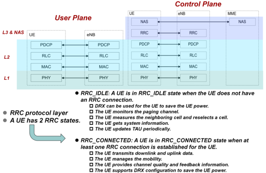
Function of RRC layer.
The RRC (Radio Resource Control) layer is essential for managing several key functions within LTE networks. It handles system information broadcasting, allowing UEs to receive necessary details about the network. It also manages PLMN (Public Land Mobile Network) and cell selection processes, ensuring that UEs connect to the appropriate network and cell. Admission control is another critical function of the RRC layer, determining whether a UE can be granted access to the network based on current resource availability.
The RRC layer also oversees security management, implementing measures to protect data and communication. Additionally, it handles cell reselection, guiding UEs to switch cells when necessary, and processes measurement reports from UEs to monitor network performance.
The RRC layer also manages handovers and overall mobility, ensuring seamless transitions between cells. It facilitates NAS (Non-Access Stratum) transport, conveying higher-layer messages between the UE and the core network, and conducts radio resource management, optimizing the use of available radio frequencies.
Function of PDCP layer.
The PDCP (Packet Data Convergence Protocol) layer has distinct functions for both control and user planes. In the control plane, the PDCP layer is responsible for encryption and integrity checking, ensuring that control messages are secure and unaltered.
In the user plane, the PDCP layer performs IP header compression to reduce the overhead of IP packets, encryption to secure user data, and sequencing and duplicate detection to maintain the correct order of data packets and eliminate duplicates.
Function of RLC layer.
The RLC (Radio Link Control) layer operates in three modes:
Transparent Mode (TM), Unacknowledged Mode (UM), and Acknowledged Mode (AM). The RLC layer handles segmentation and re-assembly, breaking down data packets into smaller segments for transmission and reassembling them at the receiver end.
It also performs concatenation, combining multiple smaller packets into one larger packet for efficient transmission. In AM, the RLC layer conducts error correction through ARQ (Automatic Repeat Request), ensuring reliable data delivery by retransmitting erroneous packets.
Function of MAC layer.
The MAC (Medium Access Control) layer is responsible for mapping logical channels to transport channels and multiplexing data streams. It also implements error correction through HARQ (Hybrid Automatic Repeat Request), which combines retransmissions with error correction coding to enhance reliability. The MAC layer conducts QoS (Quality of Service) based scheduling, prioritizing data flows based on their QoS requirements to ensure optimal performance.
Function of PHY layer.
The PHY (Physical) layer performs several critical functions related to the physical transmission of data. It detects errors in received data, applies FEC (Forward Error Correction) encoding and decoding to correct errors, and performs rate matching to adjust the transmission rate to the available bandwidth.
The PHY layer maps data to physical channels, applies power weighting to manage transmission power, and conducts modulation and demodulation to convert data between digital and analog forms. It also handles frequency and time synchronization, ensuring that transmissions are aligned correctly.
Additionally, the PHY layer performs radio measurements, processes MIMO (Multiple Input Multiple Output) transmissions, implements transmit diversity, performs beamforming to direct signals towards specific UEs, and conducts RF (Radio Frequency) processing for the actual transmission and reception of signals.
E-UTRAN Protocol Stack – S1 Interface.
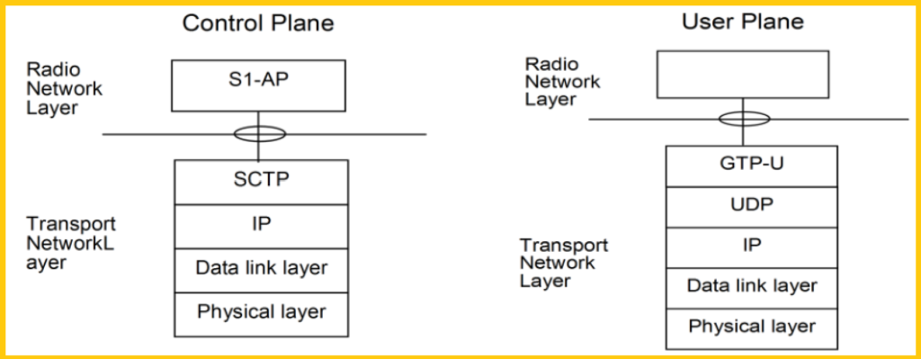
The S1AP (S1 Application Protocol) is an application layer protocol that facilitates communication between the eNodeB (Evolved Node B) and the MME (Mobility Management Entity). It is a critical component in the LTE network architecture, enabling the exchange of signaling messages necessary for managing connections and mobility.
The SCTP (Stream Control Transmission Protocol) is used to ensure the reliable delivery of these signaling messages over the S1 interface between the MME and the eNodeB. SCTP provides transport layer services, ensuring message ordering, loss detection, and retransmission capabilities, which are essential for maintaining robust and reliable signaling communication.
GTP-U (GPRS Tunneling Protocol-User Plane) is utilized for user data transmission between the eNodeB and the S-GW (Serving Gateway). GTP-U encapsulates user data packets and tunnels them through the LTE network, ensuring that user traffic is efficiently routed to its destination.
The UDP (User Datagram Protocol) is used for user data transmission in certain contexts. UDP is a transport layer protocol that provides a connectionless data transmission service, which is suitable for applications where low latency is crucial, even if it comes at the cost of potential packet loss.
The data link layer can utilize transport layer 2 technologies such as PPP (Point-to-Point Protocol) and Ethernet. PPP provides a standard method for transporting multi-protocol datagrams over point-to-point links, while Ethernet is a widely used technology for local area networks, offering high-speed data transfer and a standardized frame structure for network communication.
E-UTRAN Protocol Stack-X2 Interface.
The X2 interface in LTE networks plays a crucial role in facilitating direct communication between neighboring eNodeBs (Evolved Node Bs). It is divided into two parts: the user plane (X2-U) and the control plane (X2-C).

X2-U (User Plane): It is required to have the same functionalities and characteristics as the S1-U interface.
X2-C (Control Plane): It is required to have the same functionalities and characteristics as the S1-C interface.