We have following Downlink parameters and features optimization for LTE and LTE Advance.
- Initial DL MCS Selecting Optimization.
- DL AMC Optimization.
- PUCCH Optimization.
- PDCCH Optimization.
- 256 QAM.
1. Initial DL MCS Selecting Optimization.
| MML Object | Parameter ID | Recommendation | Function |
| CELLCQIADAPTIVECFG | HoAperiodicCqiCfgSwitch | ON | eNB trigger aperiod-CQI after Handover Complete, to obtain the UE DL channel condition timely and then do the MCS adjustment. |
| CELLDLSCHALGO | HoStaticMcsTimer | 10 | Once eNodeB obtain the DL CQI after handover, eNodeB can do the MCS adjustment timely. |
| CELLDLSCHALGO | CqiAdjInitialStep | 100 | When IBLER is below 5% after access and handover, eNB use the bigger CQI adjust step which is 10 times as normal CQI adjust step. |
| CELLALGOSWITCH | RptCqiFltInitSwitch | ON | the initial filtered value of the reported CQI is determined based on the CQI value reported by the UE, the eNB can reach the suitable MCS fast. |
| CELLALGOSWITCH | DlCqiAdjDeltaOptSwitch | ON | Fixed the CQI adjust period defect in medium and high load scenarios. If this option is selected, the IBLER convergence performance improves and downlink throughput increases. |

MCS=[α *CQI_old+(1- α)*CQI_new]+CQI_Adjust_Old+ΔCQI*Step
α : Filter coefficients, default value is 0.25;
CQI_old: if RptCqiFltInitSwitch is ON, the initial CQI_old is adaptive by initial CQI reported from UE:
• When initial CQI is high, the initial CQI_old is higher;
• When initial CQI is low, the initial CQI_old is fixed by 4;
Step: After UE access/handover, When CqiAdjInitialStep is set 100(0.01):
• When IBLER is below 5%, the CQI adjust step will be 1, CQI adjust step can be faster than the baseline strategy than can improve the DL throughput.
• If the IBLER is above 5%, the CQI adjust step strategy will follow the baseline strategy.
CQI_Adjust_Old: the default initial value is -4;
ΔCQI: determined by IBLER;
After the Initial MCS Selecting Optimization, the DL throughput gain after Handover between 1 sec.
| Case | Scenario | RSRP | SINR | AVG_MCS_DL | DL IBLER | Rank Ratio | DL RLC Throughput (kbps) | Gain |
| ① | Off | -86.79 | 6.23 | — | — | 16.96% | 13232.84 | 9% |
| On | -84.00 | 5.67 | — | — | 63.18% | 14426.10 | ||
| ② | Off | -84.44 | 5.87 | 12.49 | 10.1 | 67.3% | 9715.68 | 8.6% |
| On | -83.69 | 5.84 | 12.91 | 10.6 | 67.1% | 10552.16 | ||
| ③ | Off | -96.59 | 6.10 | 11.25 | 9.57 | 54% | 19631.62 | 10% |
| On | -96.57 | 6.70 | 11.67 | 10.01 | 56% | 21697.26 |
2. DL AMC Optimization.
| MML Object | Parameter ID | recommendation | Function |
| CELLALGOSWITCH. CqiAdjAlgoSwitch | AdaptiveStepVarySwitch | 1 | . |
| DlEnVarIblerTargetSwitch | 1 | ||
| DlCqiAdjDeltaOptSwitch | 1 | When in the high-loaded scenario (user number is higher than 20(LBBPc) and 150 (LBBPd), open the Switch to recover the CQI adjust step as low-loaded. |
DL AMC Optimization – DlCqiAdjDeltaOptSwitch
Low MCS Climb in high-loaded Scenario.

WideCQIOri0:4bit Wide CQI
CFI:PDCCH symbol Num
TB0_ACK0: Code0 HARQ 1:ACK 2:NACK 0:DTX
TBSAdj0: Code0 I TBS


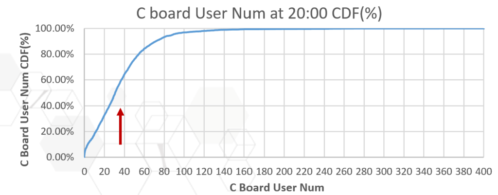
CQI adjust Period extend and MCS climb slowly when C Board User Num >=20. MCS adjust slowly after CQI adjust Period extend.
Downlink CQI Adaptive Step Optimization.
When the radio channel quality suddenly changes, the downlink MCS is not adjusted timely based on the usual adjustment step, and MCS is not proper for a while.
Solution:
According to the number of the continuous ACK/NACK feedback, the downlink MCS will be adjusted timely with the adaptive adjustment step.
For example, when the radio channel quality suddenly becomes better from MCS=8 to MCS=11, if the number of the continuous ACK feedback received is greater than a certain value, the adjustment step will be doubled, and then it accelerates the convergence of IBLER.
Impact.
Downlink CQI adaptive step optimization Algorithm will benefit the convergence of IBLER with the DL channel change.
The KPI counter IBLER and RBLER may increased.

Drive test
Turn on AdaptiveStepVarySwitch of CQI Adjustment, just as the blue line. Gain of user downlink throughput is 2%(52.7Mbps->53.8Mbps).


Downlink Flexible IBLER Target adaption Enhancement.
The IBLER target for downlink is fix to 10% in the early version. It is best for most scenario, not for all the scenario. When the CQI fluctuation is lower, IBLER is better lower than 10%. When the CQI fluctuation is higher, Ibler is better higher than 10%.
Solution.
The solution adjusts the downlink IBLER target based on the channel fluctuation characteristics and the channel quality. eNodeB identifies channel fluctuation characteristics based on the UE-reported channel quality indicators (CQIs). And the channel quality is configurable.
If the channel fluctuation is large and the user is at a far point, the eNodeB increases the downlink IBLER target value of this user. If the channel fluctuation is small and the user is at a near point, the eNodeB decreases the downlink IBLER target value of this user.
Activate
MOD CELLALGOSWITCH:LOCALCELLID=0,CQIADJALGOSWITCH=DlEnVarIblerTargetSwitch-1;
MOD CELLDLSCHALGO:LOCALCELLID=0, LOWIBLERTARGETTBSIDXTHLD=21;
MOD CELLDLSCHALGO:LOCALCELLID=0, HIGHIBLERTARGETTBSIDXTHLD=5;
3. PUCCH Optimization.
| Parameter ID | Command | Description |
| PucchCloseLoopPcType | MODCELLPCALGO | MOD CELLPCALGO: LocalCellId=0, PucchPcPeriod=1; Note that changing PucchPcTargetSinrOffset from 0 to 10 will cause increased PUCCH interference. If the network load is heavy, it is recommended to keep it at 0; MOD CELLALGOSWITCH: LocalCellId=0, UlPcAlgoSwitch=PucchPcDtxSinrSwitch-1&OuterLoopPucchSwitch- 1; CELLALGOSWITCH. PUCCHINITIALPCSWITCH@ULPCALGOSWITCH ========Normal commercial scenario, network without external interference scenario============== MOD CELLULPCCOMM: LocalCellId=0, P0NominalPUCCH=-115; MOD CELLPCALGO: LocalCellId=0, PucchCloseLoopPcType=NOT_USE_P0NOMINALPUCCH; ========The network has external interference scenarios============== MOD CELLPCALGO: LocalCellId=0, P0NominalPUCCH=-105; MOD CELLPCALGO : LocalCellId=0, PucchCloseLoopPcType=USE_P0NOMINALPUCCH; Note: The Pucch power control target SINR offset is currently set to 0. After the site construction is completed and the load is reduced, the power control target value can be set to 5 or 10. |
| PucchPcPeriod | MOD CELLPCALGO | |
| UlPcAlgoSwith. PucchPcDtxSinrSwitch | MODCELLALGOSWITCH | |
| P0NominalPUCCH | MODCELLULPCCOMM | |
| PUCCHINITIALPCSWITCH@ULPCALGOSWITCH | CELLALGOSWITCH | |
| PUCCH IRC and IRC enhancement | MOD CELLALGOSWITCH: LocalCellId=0, IrcSwitch=PucchIrcSwitch-1; MOD CELLALGOSWITCH: LocalCellId=0, PucchIRCEnhance=ON; |
PUCCH IRC & IRC Enhance.
Interference Rejection Combining (IRC)
IRC is a diversity combining technology which now is introduced in eRAN 6.0 for PUCCH to enhance performance.
Two Receive Technologies.
Maximum ratio combining (MRC)
- A common receiver which is the optimal if interference is spatially white.
Interference rejection combining (IRC)
- An advanced receiver developed from MRC.
- High performance if interference is spatially coloured.
- IRC use interference mitigation technology to improve receive performance.

MOD CELLALGOSWITCH: LocalCellId=0, IrcSwitch=PucchIrcSwitch-1;
MOD CELLALGOSWITCH: LocalCellId=0, PucchIRCEnhance=ON;
4. PDCCH Optimization.
| MMLObject | ParameterID | recommendation | Function |
| CELLPDCCHALGO | AggLvlSelStrageForDualCW | STRATEGYBASEDONCAPACITY | In normal networks, STRATEGYBASEDONCAPACITY can keep the balance of CCE level and reliability, to keep the DL throughput. |
| PdcchMaxCodeRate | 75 | Keep the default value to keep a reliability on PDCCH | |
| PdcchCapacityImproveSwitch | ON | Increase the initial value for closed-loop adjustment on PDCCH aggregation level, save the CCE and CFI, to improve the DL throughput. | |
| HYSFORCFIBASEDPRESCH | 0 | a pre-allocation failure does not trigger an increase in the number of CFIs, to improve the DL throughput. |
4. PdcchCapacityImproveSwitch Optimization
CCE_Level=MCS_Adjusted+CCE_Initial+ΔCCE.
MCS_Adjusted: from PDSCH CQI adjust result.
CCE_Initial: if PdcchCapacityImproveSwitch is ON, the initial CCE_Initial is 0 , otherwise is -10;
Δ CCE : determined by DTX Result

PdcchCapacityImproveSwitch on can reduce near point UE CCE Level and decrease CCE Usage and CFI Number.
PDCCH Code Rate Optimization.
Our main Objective to Decrease symbol number for PDCCH and increase the symbol number for PDSCH, which can improve DL throughput in the middle or heavy traffic network.
Increase PDCCH max code rate from 0.75 to 0.95.
PDCCH CCE1 can be used in Max Code Rate 0.95, that will increase the usage of CCE1, decrease the usage of CCE2/4/8. As the result the symbol numbers of PDCCH will decrease, the symbol numbers for PDSCH.
Observation
Basic performance of network is not affected. The CCE aggregation level 1 Ratio should be increased. Compare the DT result before and after the optimization for the DL throughput gain.
Risk
PDCCH DTX Rate may increase slightly.
HYSFORCFIBASEDPRESCH for PDCCH Optimization
Indicates the hysteresis of control format indicator (CFI) number increase caused by uplink preallocation failures when the PdcchSymNumSwitch parameter is set to ECFIADAPTIONON.
MOD CELLPDCCHALGO: LOCALCELLID=0,HYSFORCFIBASEDPRESCH=0;
256 QAM.
3GPP R12 introduce the higher order modulation scheme 256QAM (Quadrature Amplitude Modulation) in DL , with 8 bits per symbol ,the DL frequency efficiency benefit is up to 33% in theory ,compared with 6 bits of 64 QAM.
64 QAM MCS 27/28 position was instead of 256 QAM MCS in protocol because of same demodulation limitation, so we can use 64 QAM MCS 27/28 ratio in live network to predict 256QAM ratio in the future.
DL 256 QAM need higher SINR , so 256 QAM is mainly used in indoor network and LOS near point for good channel condition in outdoor networks.

How to Activate DL 256 QAM in LTE?
MML: MOD CELLALGOSWITCH: LocalCellId=0, Dl256QamAlgoSwitch=Dl256QamSwitch-1&Dl256QamAccessorySwitch-1;
UL Parameter
- Near Point PUSCH CL Power Control Optimization.
- PRACH Adaptive Frequency Offset.
- UL scheduler power control&UlSchCtrlPwrUserSetOptSw.
- Carrying PHR message in inter-eNodeB HO command.
- 64 QAM.
- SRS ADAPTIVEMODE.
- UL Perceived throughput maximize AMC(PAMC).
- UL COMP.
1. NEARPOINTUEOPTPUSCHSWITCH
Before Optimization:
If there is intersystem interference in the LTE network, the SINR measurement result will be higher than the real value. As the result the UL power control will not raise the power in time. The user UL Throughput will be affected.
Enhanced Optimization:
Power control is judged by the SINR. Following the enhanced algorithm the SINR will according to the lower value between measuring SINR and CRC adjusted SINR.
| MML Command | Parameter ID | Parameter Change Type | Default | Version Requirement |
| MOD CELLALGOSWITCH: LocalCellId=1, UlPcAlgoSwitch=NearPointUeOptPUSCHSwitch-1; | CELLALGOSWITCH: | Modify | 0 | eRAN7.0 |
| CellPcAlgo. NearPointUePuschType=UlBigPktUser | CellPcAlgo | Modify | AllUser | 8.X |
2. PRACH Adaptive Frequency Offset
In default parameter configuration, the prach-FreqOffset is fixed number. For example, 15Mhz Cell PRACH offset 7, there are 6 PUSCH RB left between PUCCH and PRACH Channel when the cell users is less 5 (PUCCH=2). When PrachFreqAdjSwitch=On (self-adaption PRACH frequency Offset enable), the algorithm can avoid the PUSCH RB number left between PUCCH channel and PRACH channel.

MOD CELLALGOSWITCH:LocalCellId=XX,RACHALGOSWITCH=PrachFreqAdjSwitch-1;
UL RB performance comparison for UL FTP User in near point(15M bandwidth):
| Default Parameter | PrachFreqAdjSwitch=On |
| PRACH Sub-Frame(period 10ms) PRACH =6RB, PRACH offset=7RB, PUCCH=2RB, Available PUSCH RB Num for single User : PUSCH 60RB Other Sub-Frame PUCCH=2RB; Available PUSCH RB Num for single User : PUSCH 72RB Accumulate PUSCH RB Num/1 Sec=(72*9+60*1)*100=70800 Num | PRACH Sub-Frame (period 10ms) PRACH =6RB, PRACH offset=1RB, PUCCH =2RB; Available PUSCH RB Num for single User : PUSCH 64RB Other Sub-Frame PUCCH=2RB; Available PUSCH RB Num for single User : PUSCH 72RB Accumulate PUSCH RB Num/1 Sec=(72*9+64*1)*100=71200 Num |
3. UL scheduler power control&UlSchCtrlPwrUserSetOptSw
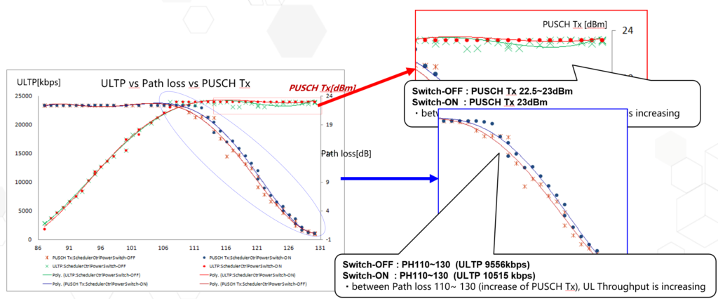
In former UL scheduler and power control design, eNB controls the UE’s PH with the target PH=0 for cell middle/edge UEs. eNB can’t get the PH information of UE at every TTI. Especially when wireless conditions has changed rapidly, the PH information maybe out-of-date.
The precision of PH report is only 1dB. Because of the above two causes, for Cell middle/edge UEs, sometimes the PUSCH transmission power is not reach the maximum power (23dBm). This leads to throughput loss.
In current UL scheduler and power control design, eNB controls the UE’s PH at the level far blow zero for cell middle/edge UEs. That is, PCALC(i) is much greater than PCMAX. So the PUSCH power is min{PCMAX, PCALC(i)}=PCMAX
For cell middle/edge UEs, the throughput will get gain.
MOD CELLALGOSWITCH: LocalCellId=0, UlSchSwitch=SchedulerCtrlPowerSwitch-1;
MOD CELLALGOSWITCH:LOCALCELLID=0,ULSCHEXTSWITCH=UlSchCtrlPwrUserSetOptSw-1;
Scheduler Power Control (Scenario 1)
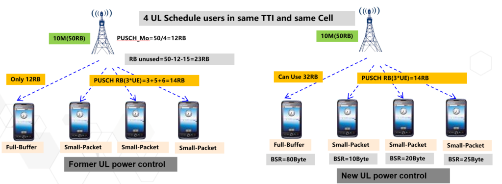
In former UL scheduler and power control design: eNB Limit PUSCH RB of user by PUSCH_Mo; (PUSCH_Mo= Available PUSCH RB/ UL schedule User Num). In some scenario: the PUSCH RB of Full-Buffer User will be limited and cannot use all available PUSCH RB due to background small Packet User ,Which result in Full-Buffer User PUSCH RB and uplink throughput loss.

New UL scheduler and power control Optimization (SchedulerControlPowerSw=On): Optimize PUSCH_M0 Calculation by UE BSR
Scheduler Power Control (Scenario 2)
PH(i) = Pcmax – Pcalc(i)
Pcmax: the maximum TX power UE can transmit, normally fixed 23dBm;
Pcalc(i): the real UE TX Power eNB calculated;
eNB keep the UE’s PH at the level far blow zero for cell middle/edge UEs.
For cell middle/edge UEs, the throughput will get gain.
So the eNB can keep the UE real TX Power at 23dBm for Full Buffer Service, to avoid the UE real TX Power fluctuation which may cause lower than 23dBm at the cell middle/edge.

4. Carrying PHR message in inter-eNodeB HO command
Before optimized:
In the scenario of inter-eNodeB handover, UE cannot report PHR info immediately after handover into the target cell because there is no PHR configure message in handover command.
Without the PHR information, eNodeB conservatively allocate limited RB for the UL data transmission which leads to the UL throughput deterioration in a short time until the PHR reconfiguration and report.
After optimized:
Carrying the PHR configure message in the inter-eNodeB HO command.
UE report PHR instantly after handover into the target cell. So that eNodeB may allocate more RB according to the PHR information and the UL throughput would be increased.
| MML Command | Parameter ID | Parameter Change Type | eRAN3.0 Default Value | eRAN7.0 Default Value | Upgrade Policy | Has Impact After Upgrade |
| MOD GLOBALPROCSWITCH: EnhancedPhrRptCtrlSw=ON; | EnhancedPhrRptCtrlSw | Modify | Null | OFF | Set to default value | No |
5. 64 QAM
64 QAM is a higher modulation than 16QAM, Accordingly distance between signal points in constellation diagram is shorter. 64QAM signal point in constellation diagram represent 6 bits, can transmit bigger TB block than 16QAM. Intensive constellation diagram require higher SINR (signal to interference plus noise ratio ), primary scenario is centre of cells.

MOD PUSCHCFG:LOCALCELLID=0,QAM64ENABLED=BOOLEAN_TRUE,R12Qam64Enabled=BOOLEAN_TRUE;
6. SRS ADAPTIVEMODE
The SRS cause UL performance loss. For peak rate it is about 10% loss for all. For UE at middle and far, the loss cause by SRS is a little less. SRS can be deactivated to improve UL performance.
There are two reasons for it. The overhead caused by SRS reduces the physical resource used for UL. There is power transient period before and after SRS symbol.
FddSrsCfgMode = ADAPTIVEMODE, SRS resource allocation can be adaptively activated or deactivated based on the cell load.
MOD SRSCFG: LocalCellId=0, SrsCfgInd=BOOLEAN_TRUE, FddSrsCfgMode=ADAPTIVEMODE;
7. UL Perceived throughput maximize AMC (PAMC)
Suitable User Initializing
Clustering users into different groups for each cell. Based on the online users, we can get the statistic characteristics (e.g. SINR Adjustment) through adaptive learning method, which can provide a better initial value for new users.

Enhanced MCS Mapping
Making full use of Receiver performance and HARQ Combing Gain, we take the channel quality and fluctuation and RB Number into consideration, an enhanced MCS mapping scheme is proposed.

MOD CELLALGOSWITCH: LocalCellId=*, UlSchExtSwitch=UlPAMCSwitch-1;
8. UL COMP
Intra-eNodeB UL CoMP
- Current UE’s UL signal could be only received and processed by serving Cell.
- CoMP is using different cells’ antennas to receive one UE’s signal, then combined different antennas’ received signals(except PUCCH,PRACH and SRS).
- Similar to use more antennas(2R->4R) in one cell to receive signals.
- Get multi-antenna signal combining gain and interference rejection gain.

MOD CELLALGOSWITCH: LocalCellId=0, UplinkCompSwitch=UlJointReceptionSwitch-1;
MOD CELLMCPARA: LocalCellId=0, ReportAmount=r1;
Service Acceleration Guarantee Under Initial Acceleration
Delay and throughput are important factors affecting user experience. The service setup delay is affected by the following factors:
- Downlink data packets, such as TCP SYN ACK and HTTP 200 OK within the DRX sleep time cannot be scheduled in time.
- Downlink data packets, such as TCP SYN ACK, cannot be scheduled in time during busy hours.
- Uplink data packets, such as HTTP GET, cannot be scheduled in time.


If a downlink data packet falls into the first DRX sleep time, it will be transmitted 35 ms later on average. If a downlink data packet falls into the second DRX sleep time, it will be transmitted 155 ms later on average.
Acceleration guarantee user identification
The eNodeB identifies acceleration guarantee users by checking the DNS and IP address accessed by a user.
Acceleration guarantee policies
After a user is identified as an acceleration guarantee user, the following guarantee policies are implemented:
The eNodeB performs continuous preallocation for the identified user. The eNodeB ensures that uplink data packets of the user are scheduled in time and downlink data packets of the user will not fall into the DRX sleep time, reducing the service setup delay.
The user is allocated high uplink and downlink scheduling priorities during the whole guarantee period, which reduces the scheduling waiting time and increases the user perceived data rate.
Acceleration guarantee policies vary depending on services. For example, Google web page browsing and PokemanGO can have different priorities.
During an inter-eNodeB handover, the identification results can be transmitted to the target cell through the X2 interface. Then, the target cell performs acceleration guarantee based on its configurations.
Stop acceleration guarantee
DL/UL Service finish or no data transmit during 30s, eNodeB will stop Accelerating this user.