While 5G networks are still in the early stages of deployment, and most commercial mobile devices don’t yet support them, Massive MIMO (MM) offers a way to significantly boost capacity and quality in existing 4.5G networks. Massive MIMO’s key features, like user-specific beams and the ability to serve multiple users on the same resources, make it an effective solution for meeting the growing demand for better user experience in terms of both capacity and quality.
However, due to the high cost and challenges of widespread deployment, it’s crucial to implement Massive MIMO in areas where it can provide the greatest benefits. This paper outlines the planning principles for selecting the best scenarios for Massive MIMO deployment to maximize its potential. We also present results from a commercial mobile network where Massive MIMO was deployed following these principles, demonstrating the gains achieved and their alignment with the planning strategies discussed.
Massive MIMO Introduction.
Data-hungry applications like Virtual Reality and Ultra High Definition Video (4K Video) are already demanding much higher network capacity and quality, leading to a surge in traffic and connections. While 5G networks are still in the early stages of deployment, and most commercial mobile devices haven’t yet fully supported them, Massive MIMO (MM) emerges as a solution to enhance capacity and quality in existing mobile radio networks.
Massive MIMO involves multi-user MIMO (MU-MIMO) systems, where base stations are equipped with a large number of antennas, typically ranging from tens to hundreds. In contrast, the LTE standard allows for only up to 8 antennas at the base station. This significant increase in the number of antennas enables Massive MIMO to scale conventional MIMO technology by one or two orders of magnitude. In a typical setup, a base station with many antennas serves multiple single-antenna users simultaneously within the same time-frequency resource.
Theoretically, such systems have the potential to significantly improve performance in terms of link reliability, spectral efficiency, and transmit energy efficiency. Additionally, Massive MIMO can reduce intra-cell interference among users sharing the same time-frequency resource by focusing transmitted power on specific users. The fundamental concept is that as the number of base station antennas increases, the channel vectors between users and the base station become very long random vectors. Under favorable propagation conditions, these vectors become pairwise orthogonal, enhancing the system’s overall efficiency.
In traditional Multiple Input Multiple Output (MIMO) techniques, a shared broadcast beam is used for all users, and time-frequency resources are shared among them, limiting capacity in proportion to the available spectrum (MHz). However, with Massive MIMO, there’s approximately a fivefold capacity gain for a 64T64R Massive MIMO system compared to a traditional 4T4R MIMO system within a similar 20 MHz bandwidth. The specific characteristics of Massive MIMO include:
a) User-specific beams for each user to enhance link quality.
b) Multiple users reusing the same resources to increase network capacity.
c) A flexible antenna pattern, with the maximum vertical Half Power Bandwidth (HPBW) reaching up to 35°, making it highly suitable for providing coverage to high-rise buildings.
In terms of radio resource capacity, a single 20 MHz TDD site equipped with 64T64R Massive MIMO is approximately equivalent to five 20 MHz TDD sites, making it a highly efficient solution for network capacity enhancement.
Massive MIMO (MM) is a promising technology for enhancing network capacity and quality, but its widespread deployment is challenging due to high costs and logistical hurdles, particularly in urban areas where installing new antenna arrays at 2.6 GHz is difficult. These challenges are especially prominent in developed countries, where existing installation spaces are often limited. Given that Massive MIMO doesn’t yield significant gains in all scenarios, it’s crucial to carefully select deployment scenarios that justify the investment.
Massive MIMO offers superior orthogonality between user channels and better channel stability compared to conventional MIMO. In scenarios with many closely located users and strong Line of Sight (LOS) to the base station, Massive MIMO can achieve a large fraction of the asymptotic capacity found in ideal Rayleigh channels, making it a strong candidate for deployment in commercial networks. Specifically, hot spot scenarios, where numerous users are concentrated in a small area with strong LOS to the base station, represent an ideal application for Massive MIMO.
In other scenarios, such as Non-Line of Sight (NLOS) conditions with rich scattering environments, Massive MIMO performs well due to improved spatial separation of users. These conditions are typical in dense residential areas where conventional LTE struggles to meet capacity and link quality demands. Massive MIMO can significantly improve performance in these environments.
Another scenario where Massive MIMO shows considerable potential is in high-rise buildings, where users are spread across multiple floors. In such cases, users on higher floors in NLOS conditions often experience poor link quality with traditional LTE. Massive MIMO can address this issue by enhancing both link quality and capacity for users located far from the base station, whether in LOS or NLOS conditions.
This article emphasizes the importance of careful planning when selecting scenarios for Massive MIMO deployment to maximize its potential benefits. We will explore these scenarios in detail, analyze the factors influencing Massive MIMO’s effectiveness, and demonstrate how prioritizing certain scenarios can lead to significant performance gains. Finally, we will present real-world deployment results from a commercial network, highlighting the gains achieved in selected scenarios based on the principles outlined in this study.
High Traffic Hotspot Scenario.
Massive MIMO (MM) is an essential solution for addressing the increasing demand for capacity and quality in mobile networks, particularly in high-traffic and capacity-constrained areas. While 5G networks are still in the early stages of deployment, and many commercial devices have yet to support it, MM provides significant advantages for 4.5G networks. By using multi-user beamforming (MU-BF) and allocating multiple users to the same resources, MM offers a significant boost in capacity, making it ideal for high-demand scenarios.
However, the widespread rollout of MM faces challenges due to its high cost and deployment complexities, particularly in developed urban areas where space constraints exist for new antenna arrays at frequencies like 2.6 GHz. Therefore, it’s critical to deploy MM in scenarios where the potential gains justify the investment.
Hotspot areas, such as famous tourist sites, main stations, shopping malls, and densely populated residential regions, are prime candidates for MM deployment. In these environments, MM’s 16-layer MU-BF capability can provide the higher downlink capacity needed to meet user demands. These sites typically experience traffic bottlenecks that MM can effectively address, leading to an immediate increase in traffic handling capacity.
Scenario 1 – Massive MIMO for Sites with Restrained Traffic
In scenarios where traffic volume is restrained due to a high number of connected users exceeding the site’s maximum capacity, Massive MIMO (MM) can significantly enhance network performance. In traditional LTE networks with limited bandwidth, this issue often arises when the number of users surpasses the capacity threshold, leading to poor user experiences as scheduling becomes constrained by limited radio resources.
To address this, it’s important to forecast future traffic and identify sites where the expected maximum number of users will likely exceed this threshold. Deploying Massive MIMO at these sites can substantially increase radio capacity—by almost five times—allowing the site to support more users without compromising user experience. As a result, traffic will also increase linearly with the number of users, as Massive MIMO provides the necessary capacity to accommodate the growing demand.
| Factors | Traffic Load | Signal Quality | Big Packet | User Dispersion | Grade | ||
| Evaluation Item | Busy Hour PRB Usage | Average CQI | Traffic size per ERAB | User Dispersion | Antenna Height(m) | User Traffic <1km Ratio | |
| Item1 | 0~20% | 0~5 | * Lowest 0%-10% | Highest 90%-100% | 0~5 | 0~30% | 0 |
| Item 2 | 20%~40% | 5~7 | Lowest 10%-30% | Highest 70%-90% | 5~10 | 30%~40% | 2 |
| Item 3 | 40%~60% | 7~8 | Middle 30%-70% | Middle 30%-70% | 10~20 | 40%~60% | 4 |
| Item 4 | 60%~80% | 8~11 | Highest 70%-90% | Lowest 10%-30% | 20~40 | 60%~90% | 8 |
| Item 5 | 80%~ | 11~ | Highest 90%-100% | ** Lowest 0%-10% | > 40 ~ | 90% ~ | 10 |
| Score Weight | 0.3 | 0.3 | 0.1 | 0.1 | 0.1 | 0.1 | |

Scenario 2 – Massive MIMO for xMbps anywhere anytime.
In certain service models, there is a specific throughput requirement for each service type. For example, to provide HD video services everywhere, the required throughput in 2017 was 4.9 Mbps. Sites where the current throughput does not meet this threshold are ideal candidates for Massive MIMO deployment. Deploying Massive MIMO in these locations can help ensure that the required throughput levels are consistently met, improving service quality for all users.
Candidate Sites Priority Ranking for Scenario 1 and Scenario 2
To determine which sites will benefit most from Massive MIMO, a priority score is calculated for each site based on various factors that influence the potential gain from MM deployment. The site with the highest score is expected to perform the best with Massive MIMO.
The priority score is calculated using the formula:
Priority Score = Σ (Score Weight * Grade)
Key Factors in the Priority Score Calculation:
- Traffic Size per ERAB: This is calculated as Total Cell Traffic divided by Total RAB Number, then divided by 1000/8. Sites with lower traffic per ERAB are given higher priority for MM deployment.
- User Concentration Rate: This measures the variance in user distribution across the cell. Sites with less dispersed users (lower variance) are prioritized.
- User Traffic <1km Ratio: This is the percentage of user traffic recorded within a 1 km radius. Sites with a higher proportion of traffic within this range are given higher priority.
- User Moving Speed: Cells with many users on the move are not ideal candidates for MM deployment, as movement reduces the effectiveness of Massive MIMO.
- User Dispersion: Higher user dispersion results in more valid beams and thus more MM gain, while lower user dispersion results in fewer valid beams.
- Antenna Height: If the antenna height is insufficient, the coverage will be limited to one vertical beam, which is not optimal for maximizing MM capacity.
By carefully considering these factors, operators can prioritize sites for Massive MIMO deployment to achieve the best possible network performance and user experience.
Priority Ranking Factors.
1. Traffic Load and Signal Quality
The benefits of Massive MIMO (MM) vary with traffic load and signal quality.
- Low Traffic Load: In scenarios with low traffic load, the primary advantage comes from Beamforming (BF), which enhances the link quality without significantly increasing capacity.
- Heavy Traffic Load: In high traffic scenarios, both Multiuser Beamforming (MU-BF) and Beamforming (BF) contribute to capacity gains. As traffic load increases, the capacity benefit from Massive MIMO becomes more pronounced. The gains also depend on the Signal-to-Interference-plus-Noise Ratio (SINR):
- Low SINR Region: The throughput improvement mainly comes from the link-level BF gain.
- Middle to High SINR Region: The MU-BF gain becomes the dominant factor, leading to greater improvements in throughput.
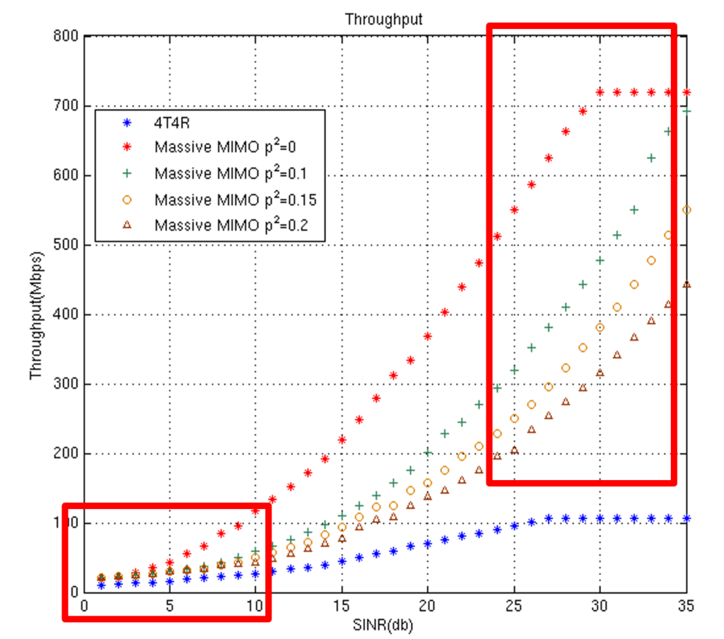
Overall, the cell throughput of Massive MIMO increases as SINR improves, with more significant gains observed in high-traffic environments.
2. User Dispersion
User dispersion significantly impacts the effectiveness of Massive MIMO.
- Low User Dispersion: When users are closely grouped, fewer valid beams can be generated, limiting the capacity gains from Massive MIMO.
- High User Dispersion: When users are spread out more evenly, more valid beams can be used, which maximizes the capacity gains from Massive MIMO. The number of valid beams is directly related to the degree of user dispersion, making this an important factor in determining the potential benefits of MM deployment.
3. Base Station Antenna Height & User Distance from Base Station.
The height of the base station antenna and the distance of users from the base station are crucial for optimizing Massive MIMO performance.
- Antenna Height: If the antenna is too low, it might only cover the area with a single vertical beam, which limits the potential capacity gains from Massive MIMO. Higher antenna placement is generally more effective.
- User Distance from Base Station: When users are far from the base station, they tend to distribute across fewer horizontal beams, which again limits the capacity benefits from Massive MIMO. To optimize performance, it’s better to have users located within an optimal range from the base station, where they can be distributed across multiple beams.
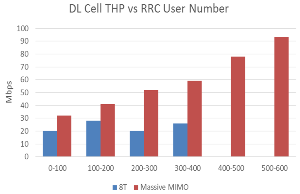
RRC User Number: Active Connected User Number.
DL Cell THP: Downlink cell throughput.
High Building Poor Coverage Scenario.
For high buildings with poor coverage, Massive MIMO (MM) deployment can offer significant gains, especially in areas like Central Business Districts (CBD), high-rise residential buildings, and luxury hotels. These areas often suffer from poor coverage due to the traditional antenna’s narrow vertical half-power beamwidth (HPBW), which struggles to provide adequate signal strength across the height of tall buildings.
To identify and select sites and buildings suitable for Massive MIMO deployment, a structured process is followed:
- Define Weak Coverage Building: A building is considered to have weak coverage if the ratio of RSRP (Reference Signal Received Power) values below -110 dBm exceeds 20%.
- Evaluate High Building’s Weak Coverage Ratio: This is done using network data, which includes electronic maps, UE (User Equipment) measurement data, and site details.
- Distinguish High Buildings: High buildings are identified based on their outline from electronic maps, with heights ranging from 30 to 160 meters and cross-sections less than 2000 m².
- Calculate Weak Coverage Ratio: For each high building, the weak coverage ratio (RSRP < -110 dBm) is calculated based on user measurement records.
| No. | Horizontal HPBW | Vertical HPBW | Antenna Gain(dBi) (±1) | |||||
| Tilt 0° | (+-)3° | (+-)6° | (+-)9° | (+-)12° | (+-)15° | |||
| 1 | 90 | 8 | 14.08 | 14.04 | 13.91 | 13.69 | 13.32 | 12.81 |
| 2 | 65 | 8 | 15.97 | 15.94 | 15.82 | 15.58 | 15.18 | 14.62 |
| 3 | 45 | 8 | 17.62 | 17.4 | 17.2 | 16.88 | 16.42 | 15.75 |
| 4 | 25 | 8 | 19.74 | 19.61 | 19.36 | 18.98 | 18.47 | 17.71 |
| 5 | 90 | 17 | 11.07 | 11.03 | 10.92 | 10.69 | 10.33 | 9.82 |
| 6 | 65 | 17 | 12.96 | 12.89 | 12.74 | 12.46 | 12.1 | 11.66 |
| 7 | 45 | 17 | 14.5 | 14.41 | 14.45 | 14.23 | 13.88 | 13.38 |
| 8 | 25 | 17 | 16.73 | 16.62 | 16.42 | 16.42 | 15.71 | 15.14 |
| 9 | 15 | 17 | 19.74 | 19.63 | 19.4 | 19.1 | 18.67 | 18.1 |
| 10 | 65 | 35 | 9.95 | – | – | – | – | – |
| 11 | 45 | 35 | 11.52 | – | – | – | – | – |
| 12 | 25 | 35 | 13.76 | – | – | – | – | – |
| 13 | 15 | 35 | 16.77 | – | – | – | – | – |
After analyzing gain scenarios and priority ranking factors for Massive MIMO site selection, it’s essential to consider antenna parameters that impact the overall gain of Massive MIMO deployment. This ensures that selected sites will benefit maximally from the deployment, providing improved coverage and capacity, especially in challenging high-rise environments.
Antenna Parameter Design to Maximize Massive MIMO Performance Gains.
Antenna pattern setting is flexible and suitable for different scenarios Pattern: 13 Types Electrical Down tilt: -15°~15. Below are commonly recommended Antenna Pattern, and Designed Parameters to maximize Performance.

Performance Comparison in a Commercial Network.
We present the performance results of Massive MIMO (MM) deployment across different sites within a commercial network. These results come from tests conducted in a live commercial network environment with typical network settings. The purpose of this comparison is to highlight the effectiveness of Massive MIMO when deployed on sites selected based on the gain methodology discussed earlier, compared to sites where Massive MIMO was deployed without considering specific gain scenarios.
The key objective here is to demonstrate that Massive MIMO shows significantly higher gains in scenarios where it is strategically deployed according to planning factors and expected gains. This is especially important when deployment needs to be selective due to the high costs and challenges associated with installing Massive MIMO technology.
Our analysis of the network and user experience data reveals that user satisfaction is notably lower in high-traffic areas, where signal quality is good, but speeds are insufficient. Additionally, coverage in high-rise buildings is often poor, leading to user complaints. To address these issues, we selected sites for Massive MIMO deployment on a TDD 20MHz carrier using the methodology outlined in the earlier sections.
The performance comparison includes results from traditional LTE, Massive MIMO in high-traffic scenarios, and Massive MIMO in low-traffic scenarios. The results show that Massive MIMO significantly improves capacity and user experience in scenarios where it is deployed with careful planning and consideration of the expected gains, confirming that strategic deployment is crucial for maximizing the benefits of this technology.
| Test Parameters | TDD 4T4R | TDD Massive MIMO – High Traffic Site | TDD Massive MIMO – Normal Traffic |
| Mechanical Down Tilt | 0° | 0° | 0° |
| Electrical Down Tilt | 7° | 7° | 7° |
| Antenna Height | 35 m | 35 m | 35 m |
| Frequency | TDD 2.6G – 20Mhz | TDD 2.6G – 20Mhz | TDD 2.6G – 20Mhz |
| MIMO | 4T4R | 64T64R | 64T64R |
| Tx Power | 40W – 4T4R | 40W – 64T64R | 40W – 64T64R |
| Cell Reference Signal(CRS) Port Number | 4 | 2 | 2 |
| Performance Comparison ( 16 Simultaneous Users ) | TDD 4T4R | TDD Massive MIMO – High Traffic Site | TDD Massive MIMO – Normal Traffic |
| Total Cell Throughput ( 16 Simultaneous Users Downloading ) | 55 Mbps | 250 Mbps | 250 Mbps |
| Single User Average Throughput ( 16 Simultaneous Users Downloading ) | 9.3 Mbps | 18.3 Mbps | 18.3 Mbps |
| User Cell Centre Throughput (Centre : 12 Users , Edge : 4 Users) 16 Simultaneous Users Centre User : 0 ~ 400m in LOS to BTS Edge user : 600 ~ 1000m NLOS to BTS | 16 Mbps | 30 Mbps | 30 Mbps |
| User Cell Edge Throughput ( Centre : 12 Users , Edge : 4 Users ) 16 Simultaneous Users Centre User : 0 ~ 400m in LOS to BTS Edge user : 600 ~ 1000m NLOS to BTS | 2 Mbps | 9.9 Mbps | 9.9 Mbps |
| User Cell Centre Link Quality (RSRP) | -92 dBm | -88 dBm | -88 dBm |
| User Cell Edge Link Quality (RSRP) | -100 dBm | -93 dBm | -93 dBm |
| Performance Comparison ( Maximum User No ) | TDD 4T4R Max User # 400 | TDD Massive MIMO – High Traffic Site Max User # 600 | TDD Massive MIMO – Normal Traffic Max User # 400 |
| Total Cell Throughput ( At Max User Capacity ) | 30 Mbps | 60 Mbps | 92 Mbps |
The performance results from the above analysis, in conjunction with the application scenarios explained in above Sections are summarized as follows:
- Total Downlink Cell Throughput: When 16 users are downloading simultaneously, the total downlink cell throughput on a Massive MIMO site is five times higher (250 Mbps) compared to conventional TDD 4T4R (55 Mbps). This demonstrates the substantial capacity gain that Massive MIMO offers.
- Cell Edge User Experience: Under the same conditions with 16 simultaneous users, cell edge users on a Massive MIMO site experience five times better throughput than those on traditional LTE sites. This highlights the significant advantage of Massive MIMO in improving user experience at the cell edges.
- Link Quality and Throughput for Cell Edge Users: On a Massive MIMO site, the link quality improvement for cell edge users is 7dB, compared to a 4dB improvement for cell center users. Similarly, the throughput improvement for cell edge users is five times greater, while it is only two times for cell center users. Therefore, when selecting a site for Massive MIMO deployment, it is crucial to choose locations with a high number of cell edge users, as these sites will benefit more from the link quality and throughput gains of Massive MIMO.
- Capacity Gains Relative to User Demand: Massive MIMO’s overall capacity gains increase as user demand rises. The results show that a site with a higher maximum user number (600 users) has a 1.5 times better total downlink cell throughput compared to a Massive MIMO site with a lower maximum user number, and three times better compared to a traditional LTE site. This confirms that deploying Massive MIMO on sites with higher capacity demands yields greater gains.
- Capacity Limitation in Traditional 4G vs. Massive MIMO: In traditional 4G networks, cell throughput stops increasing when the number of users exceeds 200. In contrast, on a Massive MIMO site, cell throughput continues to grow even when the number of users exceeds 500. This clearly illustrates the superior scalability of Massive MIMO in handling high user volumes.
- Performance Gains in High Building Scenarios: Massive MIMO deployment in high-building scenarios, such as central business districts with high-rise buildings, significantly improves coverage and user experience. RSRP improves by 5dB, and downlink user throughput increases by 100%, demonstrating the effectiveness of Massive MIMO in overcoming coverage challenges in dense urban environments.


Note : References to Different study Papers are included in this study.