1. GENERAL
2. DEFINITION OF SPOOL ERECTION DRAWING
3. SPOOLGEN SET-UP
4. SPOOL DRAWING PROVISION MATRIX
5. SPOOL NUMBERING METHOD
6. WELDING JOINT NUMBERING AND REGISTRATION METHOD
7. SPECIAL REQUIREMENT
Attachment 1
1. GENERAL
This method statement describes the methods of the preparation for piping Spool Drawings including weld joint registration for commercial buildings, plants and refinery projects. Spool Drawings, which are necessary for piping fabrication and erection work, will be produced through the application of SPOOLGEN software on this project.
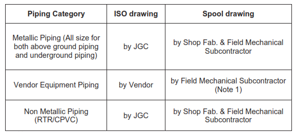
Piping work will be managed using Integrated Construction Management System (hereinafter abbreviated as iCMS) of JGC Corporation (hereinafter abbreviated as JGC) which requires importing material information and weld joint information from SPOOLGEN. Shop Fabrication Subcontractor and Field Mechanical Subcontractor shall be in charge of issuing spool drawing as per following concept.
2. DEFINITION OF SPOOL ERECTION DRAWING
Spool Erection Drawing
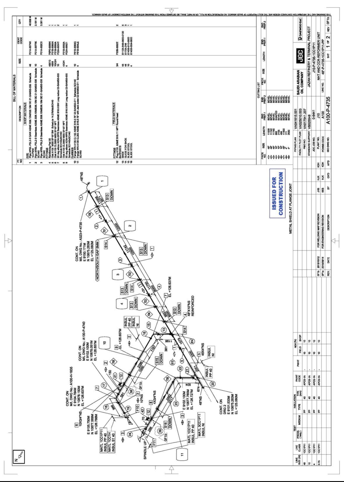
The spool erection drawing contains several spools with detailed information such as joint number with indication of field weld or shop weld, spool piece number, support information, list of material, design condition. Generally used for field erection. See Attachment-1. All information on ISO drawing shall be transferred to spool erection drawing.
3. SPOOLGEN SET-UP
SPOOLGEN SET-UP iCMS requires the importing of material information and welding joint information, which are produced by SPOOLGEN. SPOOLGEN shall be set-up so that those data suits and are ready for iCMS.
PIPING MATERIAL CLASSIFICATION
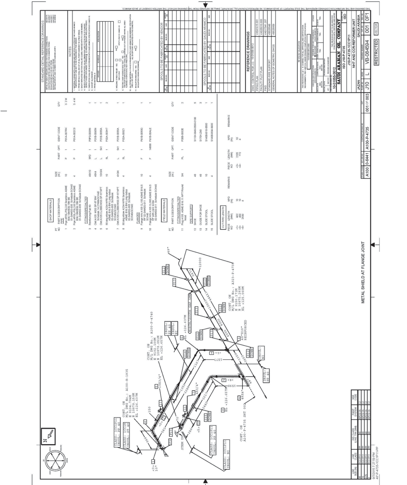
Each piping component including piping support will be classified as FIELD MATERIAL or SHOP MATERIAL on ISO and Spool Erection Drawing as shown in Attachment-1.
4. SPOOL DRAWING PROVISION MATRIX
Spool Drawing is required for the all piping ISO drawing issued for construction. Including ISO drawing which has only field erection materials.
4.1 Drawing Provision Matrix
The spool drawing will be provided in accordance with the following table.
Notes
1 : Subcontractor shall provide spool erection drawing, LOM data and weld joint information based on related ISO.
4.2 Spool Break for Piping
Non-Lined spool piece break shall be within 3.5m(H) x 14.0m(L) x 2.4m(W). Internal Lined spool piece break shall be as per JGC engineer’s Instruction.
5. SPOOL NUMBERING METHOD
Each spool piece shall be assigned a Spool Piece number in SPOOLGEN.
If spool piece is added or deleted due to revision in the spool drawing, the spool piece number shall be assigned in accordance with the following method:
a) Addition of Spool Piece
The additional spool piece number shall be continuous number of the last existing spool piece number in spool erection drawing.
b) Deletion of Spool Piece
The spool piece number for deleted spool piece shall keep as it is. However the deleted spool piece number shall not be used again.
6. WELDING JOINT NUMBERING AND REGISTRATION METHOD
6.1 Welding Joint Numbering and Registration to iCMS
Weld Joint number(s) shall be entered either manually or by the automatic numbering function available in SPOOLGEN. In general the Weld Joint number(s) shall be provided sequentially from 1 to 999 against each Spool Drawing consisted of a several sheets including Shop and/or Field weld. It is not required to segregate “Shop or Field“ by numbering. e.g.
Spool Erection Drawing “A312-MPC-3441”.
A312-MPC-3441, Sheet 1/3, Joint No. 1 to 15.
A312-MPC-3441, Sheet 2/3, Joint No. 16 to 28.
A312-MPC-3441, Sheet 3/3, Joint No. 29 to 42.
Shop/Field Flag (S/F)
In the Spool Drawing prepared by SPOOLGEN, joint will be indicated on the drawing as follows:
Shop weld: Joint No. in circle
Field weld: Joint No. in hexagon
6.1.1 Original Joints
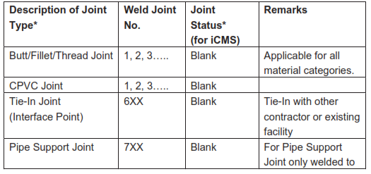
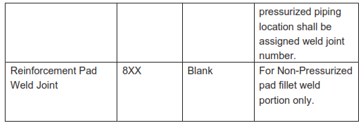
Weld Joint number(s) assigned by SPOOLGEN for a first time operation are considered as an Original Joints. Weld Joint numbers for an Original Joints are assigned by SPOOLGEN with following method:
Note: “Joint Status” Refer to 6.1.4 Joint Status.
6.1.2 Repair, Cut and Re-weld Joints
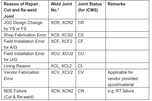
Repair, Cut and Re-weld Joints due to ISO drawing revision (YS), Field modification (FS), fabrication error, material damage, NDE failure and etc. are assigned as mentioned below:
Note: X is original Joint No. it can be 1 digit to 3 digits
For Cut & Re-weld case, Original Weld Joint No. shall be kept and just add suffix. e.g.) Original Joint No. (12), requires cut & re-weld due to RT failure, new Joint No. shall be (12CN). In addition, Joint No. (12CN) requires cut & re-weld due to RT failure, new Joint No. shall be (12CN2).
6.1.3 Joint Status (for iCMS Welding Control System Operation)
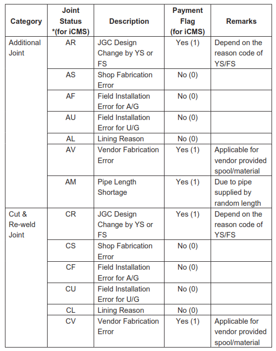
In case of Additional Joint and Cut & Re-weld Joint following “Joint Status” to be verified by the each Subcontractors and confirmed by QC/Piping Section according with following criteria:
Note: All Joint Status shall be recorded by Daily Welding Report (DWR) by QC and subcontractor to provide all necessary supporting documents for verification by QC.
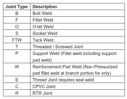
6.1.4 Joint Type
Following “Joint Type” shall be setup in SPOOLGEN and assigned by SPOOLGEN operator.
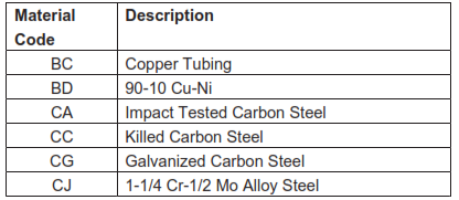
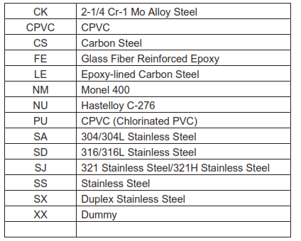
6.1.5 Material Code (for iCMS Welding Control System Operation) Following “Material Code” shall be set by iCMS Engineer in prior to set “Line Class Table Master”.
7. SPECIAL REQUIREMENTS
7.1 Revision Control Box for ISO DWG and Spool DWG
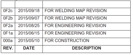
The following Revision Control box shall be indicated by using AutoCAD on Spool Drawings.
7.2 Piping with Longitudinal Weld
Pipe seam location shall be decided to avoid same weld location, such as pipe and fittings (elbow, tee reducer), also weld penetration from support pad. Preferably, the distance (circumferential offset) between longitudinal welds of adjacent pipe joints shall be 45 degrees apart.
Minimum requirement
The minimum distance between parallel butt welds shall be 20mm or three times the wall thickness of the joint, whichever is greater (Refer to SAES-W-011 Para. 11.16.1)
ATTACHMENT-1 SAMPLE SPOOL DRAWING (1/2)
ATTACHMENT-1 SAMPLE ISO DRAWING (2/2)
