Methods of Preventing Ignition
Three basic approaches are used individually or in combination to prevent ignition of hazardous atmospheres by Bently Nevada machinery information systems:
- Intrinsically Safe/Non-incendive Equipment: Eliminates the ignition source by designing equipment that cannot cause ignition when in contact with flammable or explosive atmospheres.
- Gas Purge/Hermetic Sealing: Controls the atmosphere surrounding the potential ignition source so that components are enveloped within a non-hazardous atmosphere.
- Flameproof/Explosion-proof Housing: Contains the explosion within a housing, preventing the ignition of the surrounding atmosphere.
Instrument System Certification
Safety enforcement authority’s job is made easier if the proposed equipment is certified for use in the hazardous area by a private or government testing agency. The testing agency subjects the equipment to rigorous electrical tests varying in difficulty depending on the Class, Zone, Division, and Group of hazard for which the equipment is being certified.
Over the years several testing agencies have earned the confidence of safety enforcement authorities in their respective countries. A partial listing, by country, of several major testing agencies includes the following:
| USA | CSA/NRTL, Factory Mutual System (FM), or UL |
| Canada | Canadian Standards Association (CSA) or UL |
| Europe | British Approvals Service for Electrical Equipment in Flammable Atmospheres (BASEEFA), or SIRA, or Laboratoire Central Des Industries Electriques(LCIE) |
| Japan | Japan Safety Standard (RIIS) |
| Australia | Standards Association of Australia (SAA) |
| Other | IEC International Standards(Future) |
Certification by one of these agencies is generally accepted by safety enforcement authorities within that country. Safety enforcement authorities in other countries may also accept this certification as valid for their own applications.
Since Bently Nevada monitors are powered by voltages up to 230 Vac or 120 Vdc, the possibility exists that sufficient energy to cause ignition could be released from the monitor under abnormal conditions. In extreme conditions, a Proximity transducer (without safety barriers) could be affected. Because of this, the Proximity, transducer power outputs from Bently Nevada monitors cannot be economically rendered intrinsically safe due to the stringent approvals required. However, the monitor outputs are designed to be non-incendive, a factor that has led to Division 2/ Zone 2 certification of many monitors.
For intrinsic safety barrier and galvanic isolators installations, the maximum allowable barrier-to-Proximity transducer cable length will vary depending upon the type of cable and its inherent capacitance and inductance values. For this reason, the design of all proposed intrinsically safe systems must be studied to assure that energy stored in the cables does not exceed intrinsic safety limits outlined in the barrier certificate.
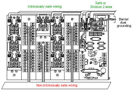
An important aspect of an intrinsically safe installation is application of measures to prevent any cross-connections between intrinsically safe and other wiring. Wiring of the two types should be positively separated by use of separated conduits or other methods to maintain separation. Wiring must also be secured to prevent possible cross-connections in the event that any wires come loose. This is good general instrumentation practice and is mandatory to achieve and maintain a working instrumentation system.
Because many safety enforcement authorities accept CSA, BASEEFA, LCIE and SIRA certification, Bently Nevada continues to submit much of its standard product line (and standard modifications) to these agencies for certification.
The certification process for new equipment requires a considerable period of time. The testing agency conducts many tests on the equipment, testing its safety for use in the area for which it will be certified. Certifications are for specific to Class, Zone, Division and Group. Equipment certified for use in a particular Class, Zone, Division and Group may not be certified when used in a different classified area.
Determine Necessary Safety Measures
Instrument System Location and Hazard Reduction Requirements
Establishing the location of system equipment is based upon many considerations. Items to consider are:
a) equipment that must be mounted at specific machine locations,
b) cable length limits between units,
c) accessibility for maintenance and operation,
d) hazard reduction measures required for a proposed area, and
e) objectionable instrument environmental factors (temperature extremes, corrosive pH, etc.).
In order to determine the hazard reduction measures required, the area classification must be known. Although plant engineers are generally able to determine area classification, the final authority rests with the local code or safety enforcement authority. Once the area has been classified (Zone and Group or Class, Division, and Group) Bently Nevada can recommend instrumentation and protective equipment suitable for installation.
Several typical installations are shown in the block diagrams in Figures 1 through 13. The equipment is shown in different areas with varying types of certifications, and the minimum protective measures that could be used for such installations. Before a system could be installed as diagrammed, however, approval from the local code enforcement authority must be obtained.
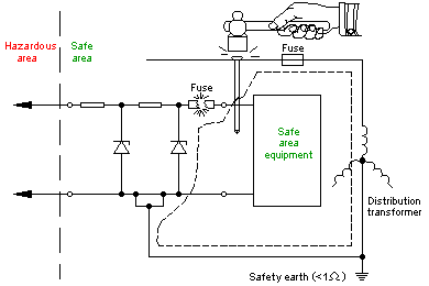
Figure 1:An example of major failure and how Barriers protect the area.
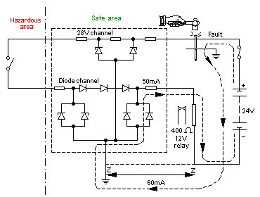
Figure 2: Another example of a fault to earth and still the equipment is protected from the fault.
Figure 3: Earth fault in a hazardous area and the Intrinsically safe ground protects the area.
Figure 4: Typical hook-up scheme for internal barrier.
Figure 5: Shows the monitor assembly in a non-hazardous area and the Proximitor and probe in a Division 2/ Zone 2 area. A protective housing is used for the Proximitor. Depending upon the specific monitor, Proximitor®, and probe, this system should be supplied as CSA or BASEEFA certified.
Figure 6: Shows an entire system located in a Division 2/ Zone 2 area. Housings are not required for the monitors except in a BASEEFA certified system, but are necessary for the Proximitor. Again, depending upon the specific monitors, Proximitors, and probes, this equipment should be supplied as a CSA, FM or BASEEFA certified system.
* If non-incendive wiring conduit is not needed.
Figure 7: This figure employs an external safety barrier between the monitor system and the transducer. The monitor and barriers are located in a non-hazardous area, the Proximitor, and probe are in a Division 1/ Zone 1 area. The Proximitors, probes and cable to the right of the barriers are intrinsically safe, requiring no additional protective equipment. Cable length is limited to not exceeding the maximum energy storage requirement for intrinsic safety. External safety barriers used by Bently Nevada are certified by one or all of the following: CSA, FM and BASEEFA. The term “external” refers to safety barriers being located outside of the rack system.
Figure 8: Figure 8 employs purging to provide a Division 2 environment for the instrument rack. Since the system shown does not employ safety barriers, the Proximitor® and probe require either explosion-proof housing (chosen for this example) or a purged housing. This system has been found widely accepted by local code enforcement authorities.
Figure 9: Explosion-proof housing – In this approach, all potential ignition sources are housed within strong, explosion-proof housings. These housings are not normally sealed gastight and usually allow leakage. In the event that a combustible concentration of flammable material leaks in to the explosion-proof housing and the instrument ignites the mixture, the housing will contain the explosion. The explosion-proof housing is designed so that the energy of the exploding gases is safely released into the hazardous atmosphere outside the housing at a temperature low enough to prevent ignition of the surrounding hazardous atmosphere. Although the housing is not perfectly sealed, its openings are small enough to quench flame and cool escaping gases.
Figure 10: This is an offering by Bently Nevada which uses internal safety barriers located directly in the system rack (see hookup schemes in figure 4). The monitor assembly (including internal safety barriers) is located in a Division 2/ Zone 2 area, with the probe and Proximitor® located in a Division 1/ Zone 2 area. The monitor assembly could also be located in a non-hazardous (or safe) area. Internal safety barriers allow you to eliminate field hardware and connections used to secure and ground external barriers. This set-up provides the best system compatibility and cost-effectiveness when compared to the use of explosion-proof housings or external safety barriers and is the preferred method of providing intrinsically safe equipment in Division 1/ Zone 1 areas.
Figure 11: Galvanic isolation approach for a system and grounding. This is a typical system and grounding of a galvanic isolation system. Notice, in this system there is no critical grounding system as in the passive barrier system and this system is intrinsically safe because of the isolation.
Figure 12: Typical grounding for passive barrier system approach. This system shows the grounding of passive barrier. Grounding is very critical for this system, because it was certified intrinsically safe with this type of grounding.
Figure 13: Typical layout of Intrinsically Safe(I.S.) wiring. Remember the spacing must be at lease 50 mm between non-I.S. and I.S. wiring.
System Approval by Local Enforcement Authority
As previously mentioned, the local safety enforcement authority makes the final determination of the, Zone and Group or Class, Division, and Group, of hazard that exists in a specific area. Once the area is classified, the instrument manufacturer must show that the proposed installation will be safe for the area and is approved by a recognized agency.
If all the equipment being installed in a hazardous area is not certified and cannot be made intrinsically safe using safety barriers, negotiation with the safety enforcement authority will result in a suitable approach to hazard reduction. Of the basic hazard reduction methods available (explosion-proof housings, purging, and non-incendive equipment), the safety enforcement authority will require one or a combination of these methods to insure a safe installation. Enforcement authorities do not have common rules that govern all installations. In granting approval on a particular installation, they may exercise personal judgment, accept certification of the equipment by a testing agency (such as CSA, BASEEFA, SIRA or LCIE) or use any other approach they deem suitable.


