1 Introduction
3 References
4 Definitions
5 Methodology
6 Preparation
7 First Cycle Analysis
8 Second Cycle Analysis
9 Final Condition Assessment Form
Motors and Generators Condition Assessment Guidelines
1. Introduction to Motors and Generators Condition Assessment
1.1 Purpose
The purpose of this article is to established general guidelines for assessing motor’s and generator’s condition of Formed Wound winding design.
1.2 Scope
This article gives the general guidelines to be followed when assessing Formed Wound motors and generators condition. The guidelines will expose the assessed machine to two cycle of analysis that requires inspecting and testing the machine in order to identify the machine final condition.
3. References Motors and Generators Condition Assessment
3.1 Industry Codes and Standards
Institute of Electrical and Electronics Engineers
IEEE Std 56 – Guide for Insulation Maintenance of Large Alternating-Current Rotating Machinery (10,000 kVA and larger)
ANSI / IEEE Std 43 – IEEE Recommended Practice for Testing Insulation Resistance of Rotating Machinery
IEEE Std 95 – Recommended Practice for Insulation Testing of Large AC Rotating Machinery with High Direct Voltage
IEEE Std 112 – Test Procedure for Polyphase Induction Motors
IEEE Std 115 – Test Procedures for Synchronous Machines
IEEE Std 522 – Guide for Testing Turn-to-Turn Insulation on Form-Wound Stator Coils for Alternating-Current Rotating Electric Machines
IEEE Std 286 – Recommended Practice for Measurement of Power Factor Tip-Up of Rotating Machinery Stator Coil Insulation
4. Definitions Motors and Generators Condition Assessment
Surge Ring: mechanical support used to counteract the coils movement and vibration. Materials selection depend on the machine size and the material could be fiber or steel.
Blocking: inserts between the winding coils and their function is to support the coils mechanically.
Laminations: stack of iron alloy sheets. The stack is mechanically supported to prevent core flexing or movement during the machine operation.
Wedges: inserts used to pressure and hold the coils in the slots preventing and coils movement.
Finger Plates: mechanical blocks used to hold core stack in place by blocking the complete stack.
Ventilations Vents: passages inside the stator and rotor cores to allow the cooling medium to pass through in order to control the machine temperature.
Slip Rings: used to provide a conductive current path for brush excitation systems or form wound rotors.
Poles Assembly: refers the synchronous motors salient rotors field coils assembly. The assembly consists of the field coils, pole cap, and V-blocks.
Field Poles: part of synchronous rotors construction and their design can be solid or laminated.
Field Coils: parts of synchronous motors rotor construction and their design varies according to the rotor construction cylindrical or salient rotor.
V blocks: part of salient synchronous motor’s rotors assembly. They are used to hold the field coils firmly against the field poles.
Retaining Rings: part of synchronous cylindrical rotor designs. The retaining rings main function is to hold and contain the field coil’s ends against mechanical and thermal stresses.
Commutator: A cylindrical assembly of insulated conductors. The commutator is used with brush type excitation to reverse the current direction through the armature.
Brushes Assembly: used with brush type excitation systems. The assembly consists from the following main parts brush, brush holders, and springs.
5. Motors and Generators Condition Assessment Methodology
The assessment will require the user to conduct two cycles of analysis before arriving to a conclusion about the machine condition. The analysis will break the machine major parts such as rotor, stator, and excitation system.
We have used this approach since machine’s internal parts vary between Induction and Synchronous machines.
Each analysis cycle will have its parameters to assess the machine condition. The First Analysis Cycle will help the user conduct a quick survey to segregate performance deficient machines from healthy machines. The healthy machines will not be inspected and tested by applying the Second Cycle Analysis.
However, machines identified as performance deficiency must be inspected and tested using the Second Cycle Analysis. The second cycle analysis will require the user to conduct detailed inspection and testing. The inspection and testing can be performed in service center or at site if possible.
Both assessment cycles will use a scoring system to tag the assessment findings with the corrective actions. The advantage of using the scoring systems is to give a quick overview about the machine condition without going through several records, especially if the assessment covers several machines.
The scoring by itself will not give an accurate assessment analysis without a subject matter expert to review the findings and proposed recommendations. There are special cases where the Fist Cycle Analysis score will result in a corrective action of replacing the machine since the existing machine condition is presenting risk to the plant safety, reliability, or operation. These cases are discussed in this Section (5).
5.1 Special Conditions
Machines showing any of the below conditions shall be considered for replacements with the completion of the First Cycle Analysis and the Final Assessment Form only. These cases must be supported with proper documents.
– Machine’s major parts cannot be duplicated for any technical reason, and the machine failure will jeopardize the plant operation.
– Machines failed catastrophically damaging the rotor and core.
– Machine repair cost will reach (70%) of a duplicate new machine.
– Machines performance is limited due to design deficiency.
5.2 Scoring
The scoring system consists of five numbers referencing a specific corrective action. The corrective action will depend in the present machine condition as described below. If the First Cycle Analysis reflects a scoring of (2, 3 or 4), then the machine is eligible to be screened using the Second Cycle Analysis. The corrective actions are briefed in Table 1.
– Score (0): No action is needed because the part or test is not applicable to the targeted machine.
– Score (1): No action needed to rectify the present situation since the existing condition will not affect the machine safety, reliability, and operation.
– Score (2): An action should be taken to further assess the machine condition while the existing condition is not presenting any risk to the machine safety, reliability, or operation
– Score (3): An immediate action should be considered because the current condition is presenting risk to the machine safety, reliability, or operation.
– Score (4): The complete machine or specific machine’s parts is should be replaced to rectify the present condition since the present situation presents risk to the machine safety, reliability, or operation.
6. Preparation
To complete the assessment on time and avoid unexpected delays, it is recommended that the user reviews his machine design and operation manual before starting the condition assessment. The objective of this initial review is to prepare any missing items needed to complete the assessment on time. The needed items could be drawings, material, testing procedures, and maintenance record.
7. First Cycle Analysis
The First Cycle Analysis will provide a quick survey to flag machines introducing any type of risk related to the machine safety, reliability, or operation. To complete this cycle analysis, the user will apply four indicators: history, inspection, vibration, and temperature trending. If the analysis shows that the existing machine condition is having or developing performance deficiency, then the machine should be assessed further using the Second Cycle Analysis.
7.1 General Information
This section is used to record the machine basic design information and capture some of machine performance data as per Table 2. The information can be extracted from the machine nameplate and SAP system.
7.2 History
The historical events are important to perform the condition assessment successfully. Therefore, a thorough review of the machine history to identify and record events such as catastrophic failures, chronic problems, or modifications. While recording the events, a brief description and specific details about the event should be added such as the failure cause, frequency, and date.
7.3 Visual Inspection
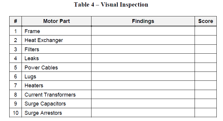
Inspect the machine listed parts and record the inspection findings using Table 4. In addition, apply the scoring criteria to specify the corrective action.
7.4 Vibration Spectrum
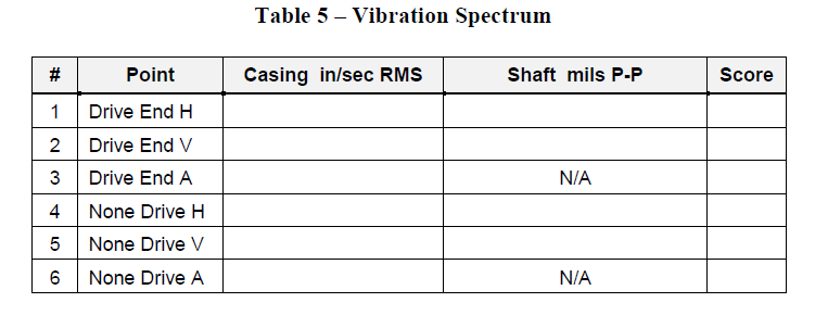
Review the machine vibration spectrum to indentify machines with existing or potential problems. The acceptable vibration limits for existing machines should be based on International Standards, Guidelines for Setting Acceptable, Alarm and Shutdown Vibration Limits. However, for newly commissioned machines the user should refer to the respected specifications. For machines with high vibration level, a further detailed analysis is needed in order to identify the source of vibration and proper corrective actions. The analysis may include shaft orbit, or bode plot. CSD/Dynamic and Reliability Analysis Unit may be contacted for help in assessing the machine condition further.
7.5 Temperature Trend
The machine bearing and winding temperature should be analyzed to verify if bearings or winding temperature readings are meeting the standard limits. Even though there are installations where the machine is not provided with permanent winding or bearing sensors, still the temperature should be measured using a laser gun, or a thermal camera.
8. Second Cycle Analysis
The Second Cycle Analysis will follow the First Cycle Analysis to assess the machine condition further after confirming the machine is having or developing a potential performance deficiency. This cycle requires detailed inspection and testing at the field or at a service center. The test and inspection data should be documented and reviewed by subject matter expert to assess the machine condition. There are three major parts that makes any electrical rotating machine: stator, rotor, and excitation system. The parts and their recommended tests are identified in the below tables.
8.1 Stator Inspection and Testing
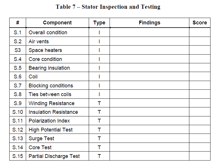
Evaluate the stator condition by performing the recommended inspections and testing. The recommended inspection and testing will verify the stator integrity mechanically and electrically. The major stator’s components to be inspected and tested are listed in Table 7, and two additional columns are provided to record the analysis findings and reference the appropriate corrective action score. The table is applicable to induction and synchronous machines. If a specific part or test is not applicable to the machine, the score section should be tagged with the number (0).
8.2 Rotor Inspection and Testing
Verify the rotor condition by inspecting and testing the rotor’s major components. The main rotor components to be inspected and tested are listed in Table 8. The rotor recommended inspections and tests should verify the rotor integrity mechanically and electrically.
There are variations between induction and synchronous rotors construction and design. The table is applicable to both types. If a specific part or test is not applicable to a specific machine, the table score should reflect number (0).

8.3 Excitation Inspection and Testing
Verify the excitation condition by inspecting and testing the excitation major components as listed in Table 9.
There are variations between brush and brushless excitation systems components design. The table is applicable to both types. If the listed part or test is not applicable to a specific excitation system, then the user should tag the scoring section with (0). The inspection and testing to be used for the rotor, will verify the winding integrity mechanically and electrically.

9 Final Condition Assessment Form
To develop the final condition assessment form, the required tables from the first and/or second analysis cycles must be completed. The objective of the final condition assessment form is to document the analysis findings and recommendations, and to have a standardized format for presenting the analysis findings and recommendations. A sample of the final machine condition assessment is attached.
Final Condition Assessment Form
| Plant Name | Machine TAG | Machine SAP Number |
| Assessment Major Findings: Write a brief highlighting the assessment major findings. |
| Assessment Major Recommendations: Write a brief reflecting the assessment recommendations and corrective actions. |
| Prepared By: | Date: |


