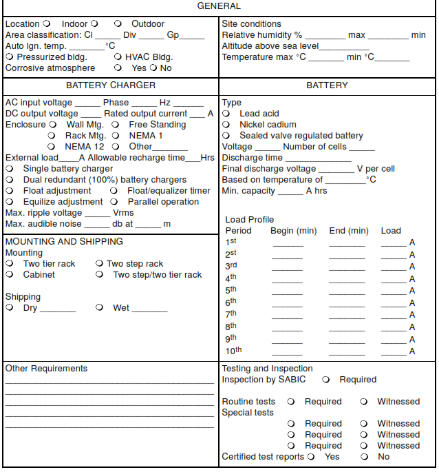
This article is for Nickel-Cadmium Battery, Vented Lead-Acid Battery, Valve Regulated Sealed Battery System, Battery Charger Design, Battery Charger Construction, battery racks, and battery chargers.
References
Institute of Electrical and Electronic Engineers (IEEE)
485 Sizing Large Lead Storage Batteries for Generating Stations for General Stations and Substations 1115 Recommended Practice for Sizing Nickel Cadmium Batteries for Stationary Applications
International Electrotechnical Commission (IEC)
IEC 62259 Secondary Cells and Batteries containing alkaline or other non-acid electrolytes-Nickel-cadmium prismatic secondary single cells with partial gas recombination
National Electrical Manufacturer’s Association (NEMA)
PE-5 Utility Type Battery Chargers
Underwriters Laboratories (UL)
UL 1564 Industrial Battery Chargers
Definitions
For the purpose of understanding this specification, the following definitions apply.
Ampere-Hour Capacity. The number of ampere-hours that can be delivered under specified conditions as to temperature, rate of discharge, and end voltage.
Constant-Voltage Charge. Charge in which the voltage at the terminals of the battery is held at a constant value. The charging current varies in accordance with the cell voltages.
Cycle of Operation. The discharge and subsequent recharge of the cell or battery to restore the initial conditions.
Discharge of a Storage Battery. The conversion of the chemical energy into electrical energy.
Equalizing Charge. An extended charge to a measured end point that is given to a storage battery to ensure the restoration of the active materials in all the plates of all the cells.
Floating Charge. A method of operation for storage batteries in which a constant voltage is applied to the battery terminals sufficient to maintain an approximately constant state of charge.
Recharge Rating. The ampere-hours output of a charger in a stated number of hours when recharging the battery for which it was intended.
Battery Requirements
- Battery Construction
The life of the battery system shall be 20 years. Nominal battery voltage shall be 125 V dc. Batteries shall be either vented nickel-cadmium, wet cell type construction, vented lead-acid, or valve regulated lead-acid sealed type, as specified in following data sheet. - Battery Sizing
Lead-acid batteries shall be sized in accordance with IEEE 485, and nickel-cadmium batteries shall be sized in accordance with IEEE 1115 using the Subtractive Method. The battery capacity shall be determined using the load profile, future growth factor, aging factor, temperature correction factor, nominal voltage, and final discharge voltage as provided in data sheet and as follows:
a. A 1.25 (25 percent) aging factor shall be applied to the calculated capacity (AH rating) to compensate for decreased battery capacity at the end of the battery’s design life
b. A temperature correction factor shall be applied to the capacity of all battery types based on the minimum temperature listed for temperatures below 25 °C (77 °F).
c. the final discharge voltage shall be 1.75 V per cell for lead-acid batteries, and 1.14 V per cell for nickel cadmium batteries -
Nickel-Cadmium Battery
The Nickel-Cadmium battery cell design can be standard vented flooded type, partial gas recombination – vented or valve regulated type. The cell design for partial gas recombination battery type shall be in accordance with IEC 62259.
https://www.youtube.com/watch?v=dxWIlwJi04I
- The battery cells shall be flat pocket plate type, consisting of powdered active materials permanently contained in finely perforated nicked-plated steel pockets that are set in steel frames, and that have an alkaline electrolyte.
- The insulation between plates shall consist of edge and intermediate plastic separators, to maintain correct spacing between positive and negative plates.
- Electrolyte level lines shall be marked on both post sides of each container, and shall be visible without obstruction when the batteries are installed in the rack.
Vented Lead-Acid Battery
- The lead-acid battery cell shall be of the Faure (pasted plate) design employing lead calcium grids.
- Insulation between plates shall consist of microporous separators combined with glass mat retainers, to maintain proper spacing between positive and negative plates, and to permit free circulation of electrolyte.
- Electrolyte level lines shall be marked on all four sides of each container.
Valve Regulated Sealed Battery System VRLA Battery
- Cell container and cover shall be made of a high impact, flame retardant plastic material equipped with a one-way low pressure relief valve.
- Each module shall be furnished with a flame arrester integral to the cover, to provide maximum safety in the event of an abnormal overcharge.
- The post seal shall be designed to prevent leakage over a wide temperature range through the life of the battery.
- Pasted plate construction shall be used for both the positive and negative plates. The grids shall be constructed of lead-calcium-tin alloy, and sized to ensure a long and reliable life. The separators shall consist of microporous glass fibers.
Battery Rack
- The batteries shall be mounted on an acid and corrosion resistant, open, two (2) step rack, suitable for back to wall mounting.
- When Data sheet indicates batteries are to be located in metal cabinets, the interior surfaces of the battery cabinets shall be treated to ensure resistance to corrosion from corrosive acids and gases. The cabinets shall have large double doors sized to allow inspection, replacement and maintenance of batteries. Cabinets shall be provided with louvers to allow ventilation of gases.
Valve Regulated Batteries
- The modular battery rack shall be welded steel units containing a maximum of 6 cells per unit. Each module shall be designed to allow air circulation between individual cells to maintain uniform cooling of each cell.
- Rack Design. The modular rack design shall allow easy installation or removal of individual cells from any module without disturbing the modular rack assembly.
- The vertically stacked height of valve regulated batteries shall not exceed 1700 mm above the floor.
- All metallic components, excluding hardware and grounding connectors, shall be coated with an acid resistant, chip and scratch resistant, baked powder epoxy of light gray color. Vendor shall supply a sufficient quantity of field-applied coating for touching up nicks.
Vented Lead-Acid and Nickel-Cadmium Batteries
- Racks shall be constructed of welded structural steel frames with bolted steel.
- All metallic rack components that are in contact with the battery shall be insulated by removable covers.
- Racks for nickel-cadmium batteries shall be coated with an alkali-resistant plastic coating.
Battery Accessories
- Vented Lead-Acid Batteries. These shall include: h. Cell and battery module lifting devices or slings for installation and removal of cells and modules weighing more than 34 kg (75 lb)
a. Thermometer
b. Hydrometer
c. Filling jar for adding distilled water
d. A set of insulated wrenches for battery post hardware
e. Spare hardware for battery racks and cell terminals
f. Supply of NO-OX terminal grease
g. All required intercell and inter-row connectors
6.7.2 Valve Regulated Lead-Acid Batteries. These shall include:
a. A set of insulated wrenches for battery post hardware
b. Spare hardware for battery racks and cell terminals
c. Supply of NO-OX terminal grease
d. All required intercell and inter-row connectors
e. Cell and battery module lifting devices or slings for installation and
removal of cells and modules weighing more than 34 kg (75 lb) - Nickel-Cadmium Batteries. These shall include:
a. Thermometer
b. Hydrometer
c. Bottle or filling jar with pour spout for adding distilled water
d. A set of insulated wrenches for battery post hardware
e. Spare hardware for battery racks and cell terminals
f. All required intercell and inter-row connectors
g. Cell and battery module lifting devices or slings for installation and removal of cells and modules weighing more than 34 kg (75 lb)
Battery Charger Requirements
Battery Charger Construction
The battery charger shall be completely assembled and wired in a freestanding enclosure as specified in above data sheet. The enclosure shall be arranged for front only operation and maintenance. Removable side panels may be provided, but rear access shall not be permissible. Provisions shall be made for conduit entrance at top and bottom. Battery chargers shall meet the requirements as per NEMA PE-5.
Battery Charger Design
- The battery charger shall be regulated silicon-controlled-rectifier type, and shall meet the following requirements:
a. Input power factor at rated output load shall be a minimum of 0.75
b. Maximum ripple shall be two (2) percent of nominal output voltage when disconnected from the battery
c. Output current shall be limited to 120 percent of rated load
d. Efficiency shall be 90 percent minimum at rated load
e. Fully filtered output
f. Individual float-and-equalize adjustments
g. Startup walk-in time shall gradually increase from 20 percent to 100 percent of rated load in 5 to 15 s after ac input power is restored
h. Battery chargers shall be capable of supplying rated load with the battery disconnected
i. When operating without the battery, the system shall meet all specified performance requirements - Battery chargers shall have automatic voltage regulating characteristics that control the dc output voltage between no load and full load to within ± 1 percent with an ac input voltage variation of ±10 percent and input frequency variation of ± 5 percent. Input voltage shall be 480 V, three phase, three wire, 60 Hz, ac.
- Battery chargers shall be current limited in both the float and equalize positions, to protect the equipment against load-side short circuits, and to prevent batteries from being overcharged.
- When the charger is connected to a completely discharged battery, output current shall not damage the charger, cause tripping of breakers, or blow fuses in the input or output circuits.
- The battery charger shall be provided with blocking diodes in the output dc circuit, to protect the battery system from back feeding the charger circuit due to an internal fault.
- Battery chargers are to be operated in parallel, they shall be provided with automatic load sharing circuitry to proportion the load within 10 percent. A disconnect switch in the output of each charger shall be provided to isolate it independently, without affecting the operation of the other charger or the load.
Industrial Battery Charger Design Video Click Here
Controls and Meters
- An ac input on/off switch shall be provided on the front of the battery charger.
- All the indicating lights shall be cluster type LEDs with push to test circuit feature for testing all the indicating lights without interruption of output power.
- A common alarm relay shall be provided for a remote alarm. Relays shall deenergize to actuate alarms. All alarm relays shall be of Form C (1-NO/1-NC) type.
- The following control indications shall be provided on the front panel of the charger:
- Alarms. The following alarm indications shall be provided by a ‘Red’ LED or pilot light on the front panel of the battery charger.
a. AC input failure
b. Charger failure
c. Cooling fan failure (for forced ventilated units)
d. Equipment over temperature
e. Low output voltage
f. Overload shutdown
g. High output voltage
h. Equalize charge mode
i. Positive ground fault
j. Negative ground fault
k. Battery end of discharge
l. Battery breaker open. This alarm shall be activated from an auxiliary contact on the buyer furnished circuit breaker.
- A microprocessor type (LED or LCD) panel meters shall be provided to display the output current and voltage readings. Meters shall have r_1 percent fullscale accuracy.
- Ground Fault Indication. The positive and negative ground faults shall be displayed on a common meter via a switch to show the magnitude of the leakage current.

