OVERVIEW AND CONTROL HARDWARE FOR COMPRESSOR CONTROL SYSTEM
The integrated control system includes a compressor control system (CCS) incorporated on the MicroNet Plus.
SYSTEM OVERVIEW
The CCS includes the following functionalities:
• Controlled and Emergency shutdown
• Performance Control.
• Surge map
• Surge Prevention
• Surge detection
• Boost
• Surge Counter
• Surge Control
SYSTEM ARCHITECTURE
The full architecture of the CCS system can be found in the System Architecture Drawings. This overview displays the location of each PDW and CCS control systems and where they connect to.
The CCS control can be operated by hardwired signals, ModBus RS-485 communication, or through an HMI PDW. When
connected with ModBus to a DCS system the DCS can perform actions such as start, stop, reset, raise/lower setpoint and emergency shutdown.
connected with ModBus to a DCS system the DCS can perform actions such as start, stop, reset, raise/lower setpoint and emergency shutdown.
Control hardware
The CCS consists of the following components:
System Cabinet
· System chassis
· Power Supply modules
· CPU module
· 48/24 Discrete Combo Module
· 24/8 Analog module
· Analog Combo module
· Network Switch (Cisco IE3000)
· Power Supply (24VDC)
· Marshalling Cabinet
· Discrete Field Termination module
· Analog Combo Field Termination module
· Analog High density Field Termination module
· HART Multiplexer
Basic control system functions
The MicroNet Plus control is a 32-bit microprocessor-based digital controllers that is programmable for many
types of applications in the control of:
types of applications in the control of:
• Gas and Steam Turbines
• Gas and Diesel Engines
• Hydro Turbines
• Compressors
The MicroNet Controls family provides a flexible system to control any prime mover and its associated processes.
Dedicated inputs and outputs (I/O) are available onboard for key control signals while distributed I/O can be used for other less critical parameters.
Communications with the MicroNet platform are available to program and service the control as well as to interface with other systems (Plant DCS, HMI, etc.). Application code is generated by use of Woodward’s GAP program or Woodward’s Ladder Logic programming environment. A service interface allows the user to view and tune system variables. Several tools are available to provide this interface.
Communication protocols such as TCP/IP, OPC, Modbus, and other current designs are included so that the user can correctly interface the control to existing or new plant level systems.
Communication protocols such as TCP/IP, OPC, Modbus, and other current designs are included so that the user can correctly interface the control to existing or new plant level systems.
System Chassis
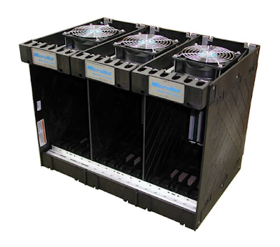
The MicroNet Plus chassis is composed of three blocks with a motherboard inserted in the back of the assembly to make connections between the fans, switches, power supplies, and control modules. The modules use the VERSA module Eurocard (VME) bus standard for connector specification and data transfer. Slot-to-slot logic and power connections are made through the etched-circuit motherboard. I/O connections are made through cables from the front of the boards to Field Terminal Assemblies in the cabinet.
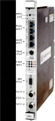
CPU Module
The CPU module runs the GAP application program. Figure below is the block diagram of the CPU module. When the power is applied, the CPU module will perform diagnostic tests, before running the application program.
MicroNet Plus Power Supply Modules
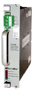
Two load sharing power supplies provide redundant power to the motherboard, CPU and I/O modules. The MicroNet Plus power supplies are 2-slot wide each and are located at each end of the chassis in the designated PS1 and PS2 slots. When redundant power supplies are running, current sharing circuitry balances the load to reduce heat and improve the reliability of the power supplies.
In the event that one power supply needs to be replaced, the recommended method for changing Power Modules is with the power off (to the module being removed and the module being inserted). The system will tolerate this “cold swap” method without failure.
48/24 Discrete Combo Module and FTM
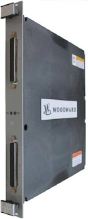
The 48/24 Discrete Combo module contains circuitry for forty-eight discrete inputs and twenty-four discrete outputs. These modules have no potentiometers and require no calibration. A module may be replaced with another module of the same part number without any adjustment.
Discrete Combo Module (HDDIO)
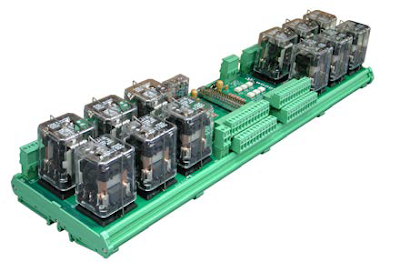
The 24/12 Discrete FTM is used with 48/24 Discrete Combo Module. The 24/12 Discrete Module has 24 discrete inputs connections and 12 SPDT relay outputs. Two FTM modules can connect to one 48/24 Discrete Combo Module to provide connections for all the IO on the module.
24/8 Analog Module and FTM
The 24/8 TMR Analog module contains circuitry for twenty-four analog (4-20mA) inputs (2-pole 10ms filter on all input channels) and eight analog (4-20 mA) outputs. These modules have no potentiometers and require no calibration. A module may be replaced with another module of the same part number without any adjustment.
The TMR 12/4 Analog FTM is used to connect up to three redundant TMR 24/8 Analog Modules to simplex I/O field wiring. As this FTM is designed to connect up to three modules, one connector will be left unused for redundant use.
Analog Combo Module and FTM
Each High Density Analog Combo module contains circuitry for 4 speed sensor inputs, 8 analog inputs, four analog outputs, and 2 proportional actuator driver outputs. Each speed sensor input may be from a magnetic pick-up or from a proximity probe, each analog input may be 4–20 mA or 0-5 V, and each actuator driver may be configured as 4–20 mA or 20–160 mA.
The Analog Combo TMR FTM is utilized to connect up to three redundant TMR Analog Combo Modules to simplex I/O field wiring. As this FTM is designed to connect up to three modules, one connector will be left unused for redundant use.
