This article establishes the minimum requirements for Industrial Pressure Gauges used in process plants. Main keywords for this article are References Pressure Gauges. Definitions Pressure Gauges. Pressure Gauges Design Requirements. Materials Pressure Gauges Design. Installation Pressure Gauges.
References Pressure Gauges
Reference is made in this article to the following documents.
American Petroleum Institute (API)
RP 551, May 1993, Process Measurement Instrumentation
American Society of Mechanical Engineers (ASME)
ASME/ANSI B40.1 Gauges-Pressure Indicating Dial Type – Elastic Element
Definitions Pressure Gauges
Bellows.
A pressure sensing element generally of cylindrical shape whose walls contain deep convolutions, and for which the length changes when a pressure differential is applied.
Bourdon Tube.
A pressure sensing element consisting of a twisted or curved tube of noncircular cross section which tends to be straightened by the application of internal pressure.
Diaphragm Seal.
A thin flexible sheet of material clamped between two body halves to form a physical barrier between the instrument and process fluid.
Receiver Gauge.
A gauge, calibrated in engineering units, which receives the output of a pneumatic transmitter.
Seamless Tubing.
Tubular products made by piercing and drawing billet, or by extrusion.
Span.
The algebraic difference between the upper and lower range values.
Suppressed Ranges.
A suppressed range is an instrument range which does not include zero.
Pressure Gauges Design Requirements in Process Industry
- Pressure gauges shall conform to ASME/ANSI B40.1.
- The gauges shall pass Vibration Test (A3.10) and Fatigue Test (A3.13) in accordance with ASME/ANSI B40.1.
- Pneumatic air receiver indicating gauges shall conform to ASME/ANSI B40.1, Grade 2A.
- The accuracy shall be ± 1% of span or better.
- The dial diameter shall be 100 mm, 4 inches, or 4-1/2 inches. Other diameters may be considered for special applications.
- The pressure connection socket shall be provided with wrench flats.
- The pressure range of the element and the element material shall be stamped on the socket.
- Pressure gauge measuring elements generally shall be C type Bourdon Tube. Bourdon Tubes shall be made from ‘drawn’ seamless tubing. The use of other types of elements (for example: Bellows, Spiral/Helical Tube, or Diaphragm) shall be selected considering range, accuracy and process fluid requirements. The use of TIG (Tungsten Inert Gas) welded tubes requires approval.
- Diaphragm seals shall be all-welded-designed for continuous duty. The diaphragm seal shall be welded to the upper half of the diaphragm seal body. The design shall be approved.
Materials Pressure Gauges Design
- Hardened type 316 Stainless Steel shall be used for measuring element and socket unless otherwise indicated. The gauge scale shall be 1.3 times the maximum pressure reading. The gauge shall withstand this pressure without a
permanent deformation of the measuring element that affects the gauge calibration. - Movements shall be constructed of stainless steel.
- The case shall be solid-front, weatherproof and furnished with a blow-out disc. All cases shall be made of low-copper aluminum (0.6 percent copper maximum), stainless steel, or phenolic. Other case materials shall be approved
- The gauge window shall be double-strength shatter-resistant safety glass. The window shall have a resilient gasket on the bezel side, held in place from the case side by a threaded retraining ring.
- The draft gauges shall be vertical edgewise type. The element shall be made of phosphor bronze.
- The gauges used on instrument air supply and air transmission signals from transmitters shall use Copper alloy measuring element or as recommended by the manufacturer.
Installation Pressure Gauges
- The installation of pressure gauges shall conform to API RP 551.
- The movement shall be constructed so that it can be easily disassembled for pinion replacement or other repairs. It shall be mounted on an extension of the socket and independent of the case.
- Local gauges shall have wall mounting cases with bottom pressure connection.
- Panel mounted gauges shall have flush mounting cases with rear pressure connection.
- Socket shall be of Bar-stock type, unless otherwise indicated.
- A stop pin shall be required on all pneumatic receiver gauges at zero (0) pressure indication.
Operation Pressure Gauges
- The maximum operating pressure shall be approximately 65 percent of the measuring range and shall not exceed 75 percent of the full scale range. Failure to select a gauge within these criteria may result in fatigue failure of the Bourdon or Bellows.
- The gauge pointer shall be adjustable without removing it from its shaft.
- Movements shall be zero and span adjustable.
- A visible stop pin shall be used to restrict the upper limit of the pointer travel. The stop shall be located at the six (6) o’clock position on the gauge front.
- Liquid filled pressure gauges used where excessive vibration is encountered, shall conform to ASME/ANSI B40.1.
- Liquid filled gauges shall have small vapor space for thermal expansion of the liquid fill. Vapor space shall be adequate to allow gauge to operate satisfactorily without leakage under the full range of ambient and process conditions specified.
- Fill fluids used in liquid filled gauges shall be selected carefully, and accounted for both process and ambient temperature limits. Glycerin or Silicon fill fluids shall not be used in applications involving strong oxidizing agents (for example: chlorine, nitric acid, or hydrogen peroxide) because of spontaneous chemical reaction, ignition or explosion. Fluorolube shall be specified in these applications. Fill fluid shall be reviewed and approved.
- The gauges shall be isolated from the following process applications by using Diaphragm Seals:
(i) Slurries, viscous or corrosive services.
(ii) Flammable or toxic streams in high pulsating/vibrating service. - Pressure gauges shall not have suppressed ranges.
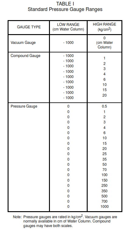
- The pressure gauge range shall be selected from Table I.
