The SEL-411L is a comprehensive protection relay that offers differential line protection among other functionalities. Testing this relay involves several steps to ensure its proper functioning in protecting power lines.
SEL411L Testing Procedure.
First of all, Install “AcSELerator QuickSet” and make the setup. Use serial cable C662 to communicate.
1-Open the software:

2-Choose Communication:
Before you communicate make sure the cable C662 on cross selection. Follow these steps to communicate and read the setting:
- Select Serial .
- Select your COM port .
- Select auto detect .
- Apply .
- Then OK.
After finishing communication READ the setting.
87L Setting & Configuration.
After establishing communication with the relay , Read the setting & apply the Approved setting.
87L Setting:
1- Phase Differential.
2- Negative sequence Differential.
3- Ground Differential.
One case we will take for example.
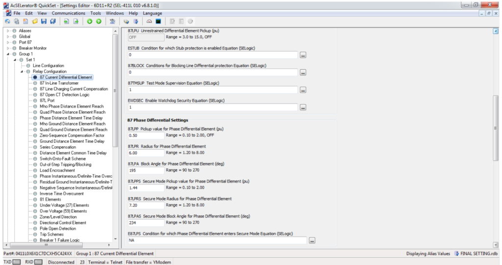
Phase Differential Setting:
| Item | Description | Setting |
| 1 | 87LPP | 0.5 pu |
| 2 | 87LPR | 6 |
| 3 | 87LPA | 195 deg |
Fill the setting as per the above information:
1- Open Group 1:

2- Configure the Line parameter:
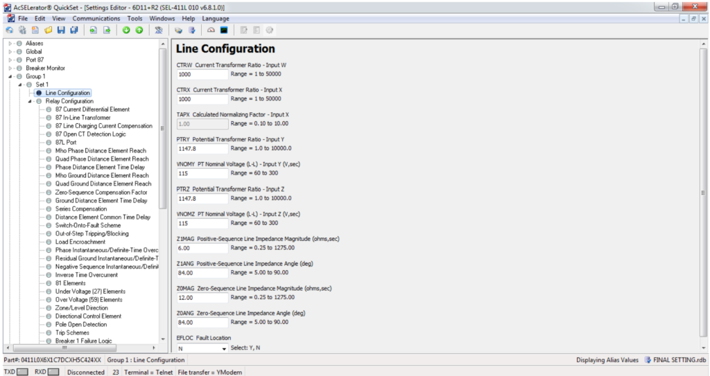
3- Disable all the function except phase differential:

4- Open 87 Current Differential & apply the setting:
5- Assign the OUTPUT GO TO INTERFACE BOARD OUTPUT:
By using Test Mode use this word bit 87TOUT.
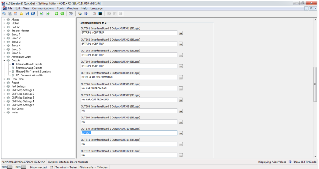
OUT310 WE USED.
For the differential test, two relays should be connected through fiber optic cable. If you have only one relay you can perform the test on Test mode through internal loopback. Do the following exercise to go to test mode loopback.
Once the relay becomes in the test mode, you can select to test the characteristic or to do a channel loopback test. The characteristic mode is used to facilitate testing of the 87L characteristic or to prevent the 87L element from interfering when testing other protection functions.
When doing the characteristic test at the local relay, the output of the differential element is blocked from driving the Trip Logic, effectively preventing the relay from closing its tripping contacts when the tested 87L operates. At the same time, the output of the element-under-test (87LA, 87LB, 87LC, 87LQ, or 87LG) is routed to the 87TOUT Relay Word bit.
Use the TEST 87L command to test the 87L communications interface (channels) or to test the 87L characteristic. Select Test L(loopback) to carry out Loopback testing on a communications channel. Select C (characteristic) to carry out testing of the 87L elements or to disable the 87L elements so that other protection elements can be tested.
In addition, the TEST 87L command allows a single relay to be tested in isolation (single-terminal test) or allows end-to-end testing of the complete87L zone (multi-terminal test). The TEST 87L command also allows you to select the particular element to be tested (A, B, C, Q, or G) and allows either the normal or secure settings to be selected for the test.
6- GO TO TERMINAL:
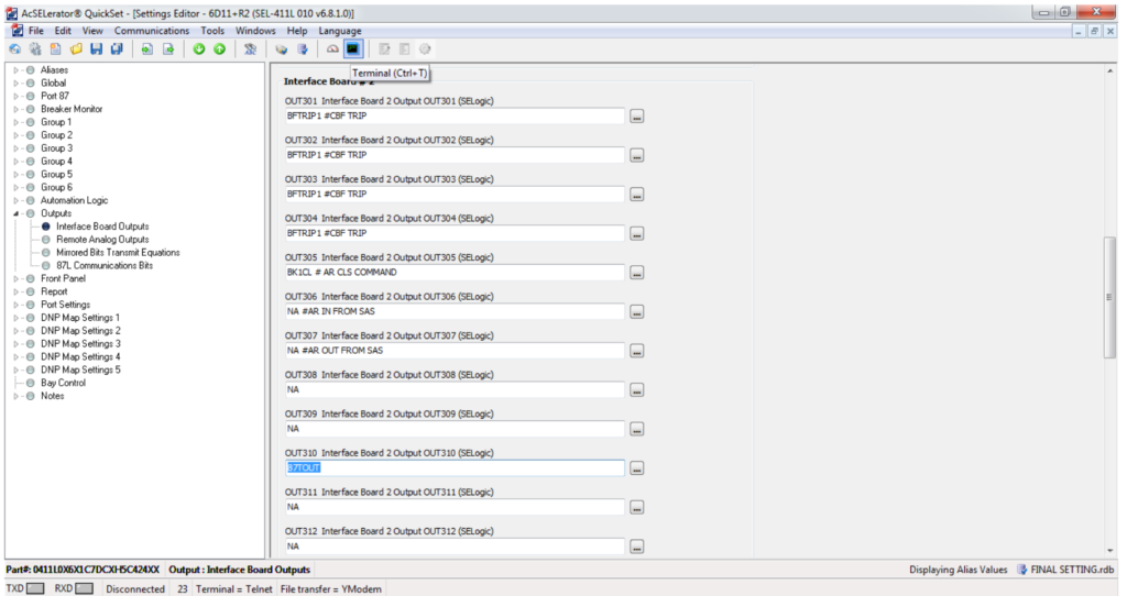
7- TEST MODE:
Write ACC and press the ENTER key to access the 1st stage of the window. Write the password: OTTER and press ENTER Now you enter into the 1st level.
To access the 2nd level/stage: write – 2AC and press the ENTER key Write the password: TAIL and press ENTER. Now you already enter into the second level and you are authorized to read the relay or give the command to the relay by proper word bits.
After entering into the Test Mode Write Test 87L and follow up these steps:

OPERATING PRINCIPLE FOR TEST MODE:
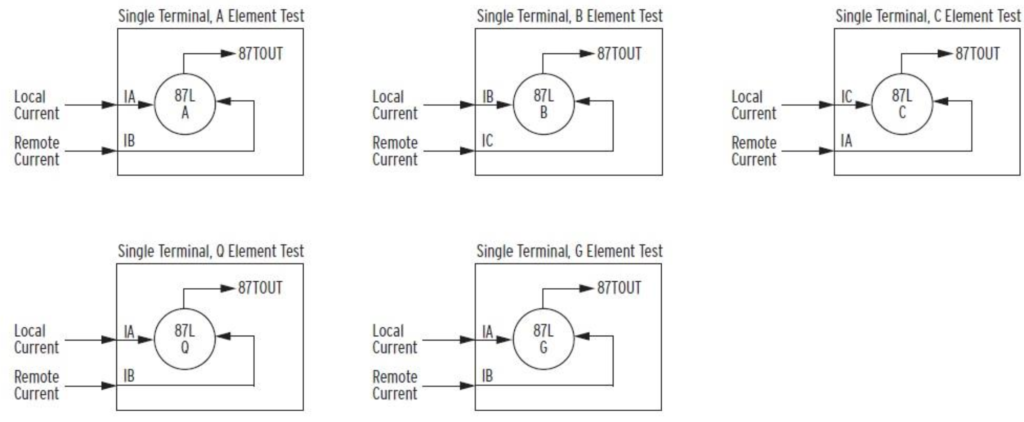
87L Testing:
Note: Before starting the test make sure to test through the switch test.
Instrument: FREJA300.

87L Elements:
1- Sensitivity Test.
2- Timing Test .
3- Alpha Plane Restrain Test.
1- Sensitivity Test:
Step1: Set ‘E87LOCTL’ =N.
Step2: Set 87L2P=OFF and 87LGP =OFF, while testing 87LPP.
Step3: Increase current on one phase until relay trips on 87. Repeat the same for other phases.
Step4: Inject one phase as differential only, no need to inject other phases as remote.
Step5: The appropriate Relay Word Bit shall be monitored on front panel or HMI.

2- Timing Test:
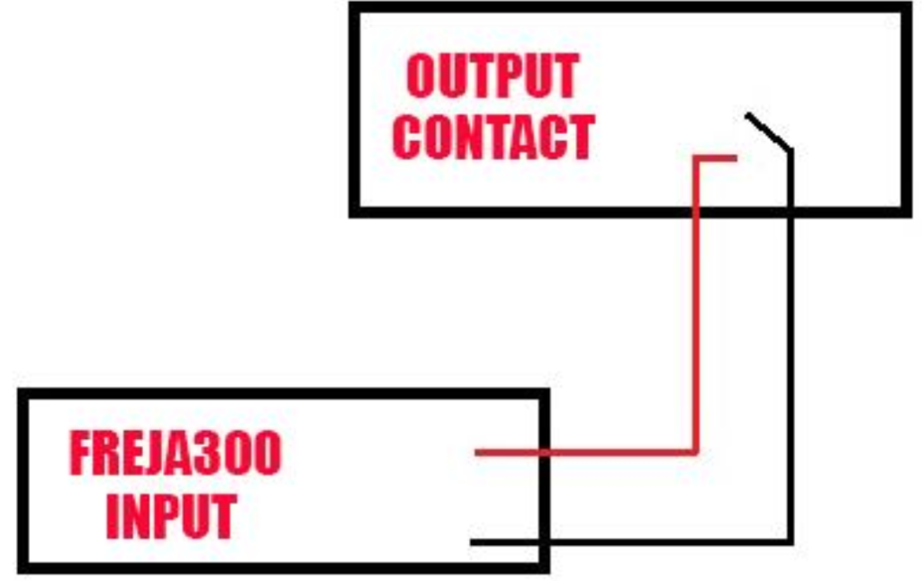
For timing take an output contact from the relay to the FREJA300 , go to second page and double the value.
| PHASE | Inject current (A) | Delay Time (ms) | Operating Time (ms) |
| A | 2x Setting | Zero (Inst) | |
| B | 2x Setting | Zero (Inst) | |
| C | 2x Setting | Zero (Inst) |
3- Alpha Plane Restrain Test:
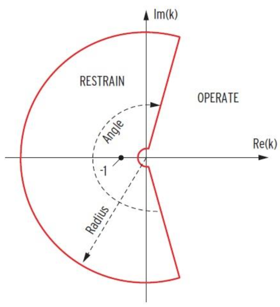
We are going to test:
Alpha Angle Test.
Alpha Radius Test (IL / IR).
a. ALPHA ANGLE TEST:
87LPP:0.5 87LPR: 6 87LPA:195 DEG
- Enable 87LPP and disable 87L2P and 87LGP for testing 87LP.
- To test phase A, Apply Phase A as local current and inject phase B as remote current.
- To test phase B, Apply Phase B as local current and inject phase C as remote current.
- To test phase C, Apply Phase C as local current and inject phase A as remote current.
- Inject local current and remote current with same magnitude and keep the local current angle to be fixed, change the angle of remote angle, or vise verse.
ALPHA RADIUS MEASURED AT ALPHA ANGLE =195 deg, with outer radius setting 6.0.

Expected Restraining angle:
Setting 87LANG=195deg,
Alpha angle = 180deg to 180-(87LANG/2)
180 +/- 97.5
Restraining angle = 82.5 to 180 deg, Operating angle = 0 deg to 180deg
Restraining angle =180 to 277.5 deg, Operating angle = 277.55 deg to 360 deg.
b. ALPHA RADIUS TEST (IL / IR).
- 87LPP: 0.5 , 87LPR: 6, 87LPA:195 DEG
- Enable 87LPP and disable 87L2P and 87LGP for testing 87LP.
- To test phase A, Apply Phase A as local current and inject phase B as remote current.
- To test phase B, Apply Phase B as local current and inject phase C as remote current.
- To test phase C, Apply Phase C as local current and inject phase A as remote current.
- Increase the remote current magnitude by fixing local current until the relay trip to find the inner radius.
- Increase the local current magnitude by fixing remote current until the relay trip to find the outer radius.
- To check the inner and outer radius, the injection of local and remote current must be in the alpha angle (195o angle side), so Inject the local current angle is 0o, and the remote current angle is 195o.
ALPHA RADIUS MEASURED AT ALPHA ANGLE =195deg, with outer radius setting= 6.0.

Expected Restraining Radius:
For Inner Radius: Inner Radius = 1 / K =1/6 = 0.1667
For Outer Radius: Outer Radius = K = 6.
Note:
Remember all of the above for testing Phase Differential current to test 87Q & 87LG enable one by one and follow the same steps ALSO from test mode make sure to choose what you need to test.
Note:
For 87Q /87LG sensitivity a single phase current shall be injected. In this case the negative
sequence (I2) or zero sequence (I0) current is equal to 1/3* Iph. But the relay compares
3 x I2_injected and 3 x I0_injected with the 87LQ / 87LGP thresholds.
By following this test procedure, you can effectively test the differential line protection function of the SEL-411L relay, ensuring reliable and accurate protection for power lines. Always refer to the specific SEL-411L manual for detailed instructions and safety precautions tailored to your equipment and testing environment.